
Methods and systems for identifying the launch positions of descending golf balls

a golf ball and launch position technology, applied in golfing accessories, devices using time traversed, instruments, etc., can solve the problems of increased manufacturing cost, increased cost of manufacture, and possible degradation of the retro-reflective surface with frequent use, and achieves reduced lighting power and intensity, and the effect of easy detection

Inactive Publication Date: 2012-02-14
LINDSAY LTD
View PDF20 Cites 15 Cited by
  • Summary
  • Abstract
  • Description
  • Claims
  • Application Information

AI Technical Summary

Benefits of technology

"The patent text describes a system for identifying golf shots using retro-reflective golf balls. These balls have a surface that reflects light in a way that makes them easier to detect by optical sensors. However, the added cost of manufacturing these balls and the potential degradation of the surface may be disadvantageous. The patent aims to provide methods and systems that can identify golf shots using standard golf balls and also work with retro-reflective golf balls. The system uses a combination of optical sensors and radar to measure the flight of the golf ball. The system can also account for differences in the dimple pattern of the golf ball to accurately detect shots. The patent also describes a method for estimating the time of impact for shots using the descent angle of the ball. Overall, the patent provides methods and systems for identifying golf shots using advanced technology."

Problems solved by technology

Secondly, at night-time or in poor ambient light conditions, the balls are much more visible to the human eye when illuminated by a light source close to the golfer.
The main disadvantages of retro-reflective golf balls include the added cost of manufacture and possible degradation of the retro-reflective surface with frequent use.
Whereas the diameters and masses of different types of golf ball are all closely similar, their dimple patterns vary significantly and this gives rise to substantial differences in carry length and flight duration under identical launch conditions.
Other dimple patterns not included in this research may well exceed these differences and the effect of surface degradation will be even more critical as the degradation becomes severe.

Method used


Image

  • Methods and systems for identifying the launch positions of descending golf balls
  • Methods and systems for identifying the launch positions of descending golf balls
  • Methods and systems for identifying the launch positions of descending golf balls

Examples


Embodiment Construction

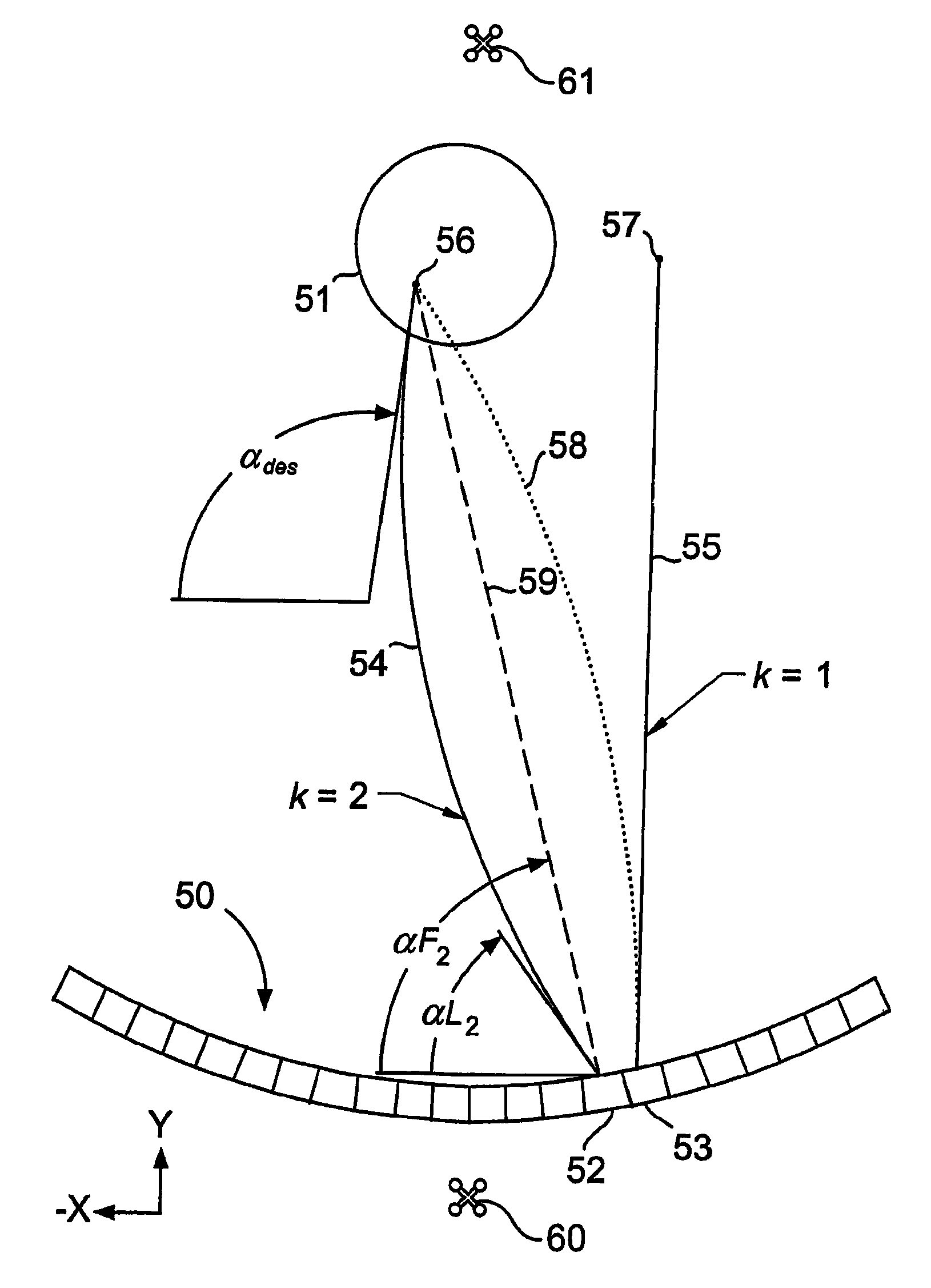
[0058]Reference axes X, Y and Z are shown for convenience in conveying orientation where this is appropriate in certain of the figures to which reference is made in the following description. In this respect, the Z-axis is vertical and points upwards, the Y-axis is horizontal and points downrange (i.e. along the general line of flight of a golf shot) and the X-axis is orthogonal to Y and Z and points in the left-to-right direction, looking downrange.

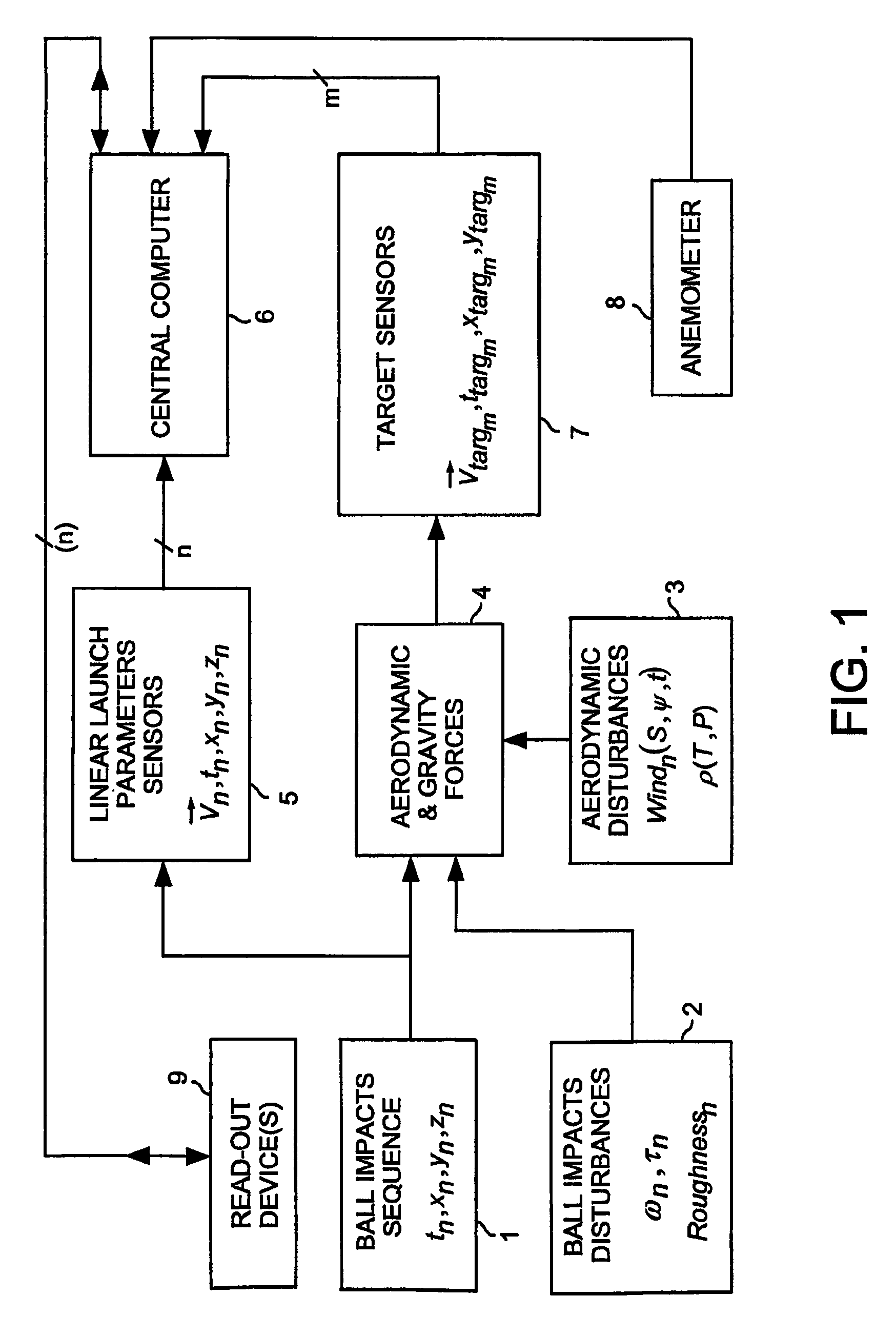
[0059]The block diagram of FIG. 1 outlines the top level system for a golf facility according to one aspect of the invention where several players hit golf balls into the same general area and sensing means are provided to identify the initial tee position of every shot.

[0060]Block 1 represents the primary input, which is a sequence of n balls hit at random times tn from random tee-off positions having co-ordinates xn, yn, and zn. Blocks 2 and 3 represent secondary inputs comprising various ‘disturbances’ or un-measured inputs such as a ...


PUM


Abstract

Identification of the tee-off bay (52;53) from which a golf ball landing on a golf-range target (51) originated, is made by calculating an estimate of flight duration (Edurk) of the descending ball as a function of the measured angle (β) of descent in elevation, and, in respect of each ball launched from the bays (52,53), comparing this estimate for a match with a measured interval between the launch of the respective ball and descent of the descending ball. The originating bay (52;53) of the launched ball for which there is the closest match is identified as the origin of the descending ball, and ambiguity or uncertainty between which bay (52,53) is identified is resolved through comparison of the measured angle (αdes) of descent in azimuth of the descending ball with estimates (Edirk) of it calculated for each launched ball, and through similar comparison in respect of a calculated decelaration ratio (Edeck) and flight duration (Durk).

Description

[0001]This application is a National Stage completion of PCT / GB2007 / 003681 filed Sep. 27, 2009, which claims priority from British patent application serial no 0712687.3 filed Jun. 29, 2007, which claims priority from British patent application serial no. 0710129.8 filed May 26, 2007, which claims priority from British patent application serial no. 0705382.0 filed Mar. 21, 2007, which claims priority from British patent application serial no. 0619014.4 filed Sep. 27, 2006.FIELD OF THE INVENTION[0002]This invention relates to methods and systems for identifying the launch positions of descending golf balls. The methods and systems of the invention have application, for example, in the context of golf shots made on golf driving ranges and other golf facilities.BACKGROUND OF THE INVENTION[0003]According the invention there is provided in one aspect a method, and in another aspect a system, for identifying in respect of a descending golf ball the position from among a plurality of launc...

Claims


Application Information

Patent Timeline
Patent Type & Authority Patents(United States)
IPC IPC(8): A63B69/36
CPCA63B24/0021A63B69/3658G01P3/68G01S5/16A63B69/3614A63B2024/0031A63B2024/0034A63B2024/0037A63B2220/35G01P3/64
Inventor LINDSAY
Owner LINDSAY LTD
Learn More