Liquid crystal display device

a liquid crystal display and display panel technology, applied in the direction of illuminated signs, display means, instruments, etc., can solve the problems of low light utilization efficiency and large thickness of backlight devices per se, and achieve high brightness uniformity and enhanced brightness distribution within the effective display area of liquid crystal display panels.

Inactive Publication Date: 2012-02-14
PANASONIC LIQUID CRYSTAL DISPLAY CO LTD +1
View PDF9 Cites 9 Cited by
  • Summary
  • Abstract
  • Description
  • Claims
  • Application Information

AI Technical Summary

Benefits of technology

[0010]A liquid crystal display device according to the present invention includes: a liquid crystal display panel in which a liquid crystal layer is sandwiched between a first light-transmitting substrate having pixel electrodes and a second light-transmitting substrate having color filters, a first polarizer is formed on a back surface of the first light-transmitting substrate, and a second polarizer is mounted on a front surface of the second light-transmitting substrate; and a backlight device which is arranged on a back-surface side of the liquid crystal display panel and supplies a light to the liquid crystal display panel. The backlight device includes: a diffusion plate which includes a light radiation surface for radiating diffusion light to the back surface of the liquid crystal display panel; a plurality of cold cathode fluorescent lamps which is arranged parallel to each other in a state that the cold cathode fluorescent lamps face a back surface of the diffusion plate in an opposed manner and radiates a light-source light to the diffusion plate, and a reflection plate which is arranged to face back surfaces of the plurality of cold cathode fluorescent lamps and reflects the light-source light radiated from the plurality of cold cathode fluorescent lamps to the diffusion plate. The plurality of cold cathode fluorescent lamps are arranged such that arrangement intervals of the plurality of cold cathode fluorescent lamps at a center portion thereof corresponding to a center portion of a display screen of the liquid crystal display panel are set larger than the arrangement intervals of the plurality of cold cathode fluorescent lamps at peripheral portions thereof corresponding to peripheral portions of the display screen of the liquid crystal display panel. Due to such constitution, the brightness distribution within an effective display area of the liquid crystal display panel is enhanced and hence, a surface-light-source light which exhibits highly brightness uniformity is radiated to the back surface of the liquid crystal display panel.

Problems solved by technology

However, the side-edge-type backlight device has a disadvantage that light utilization efficiency is low.
However, the direct backlight has a disadvantage that a thickness of the backlight device per se becomes large.

Method used


Image

  • Liquid crystal display device
  • Liquid crystal display device
  • Liquid crystal display device

Examples


embodiment 1

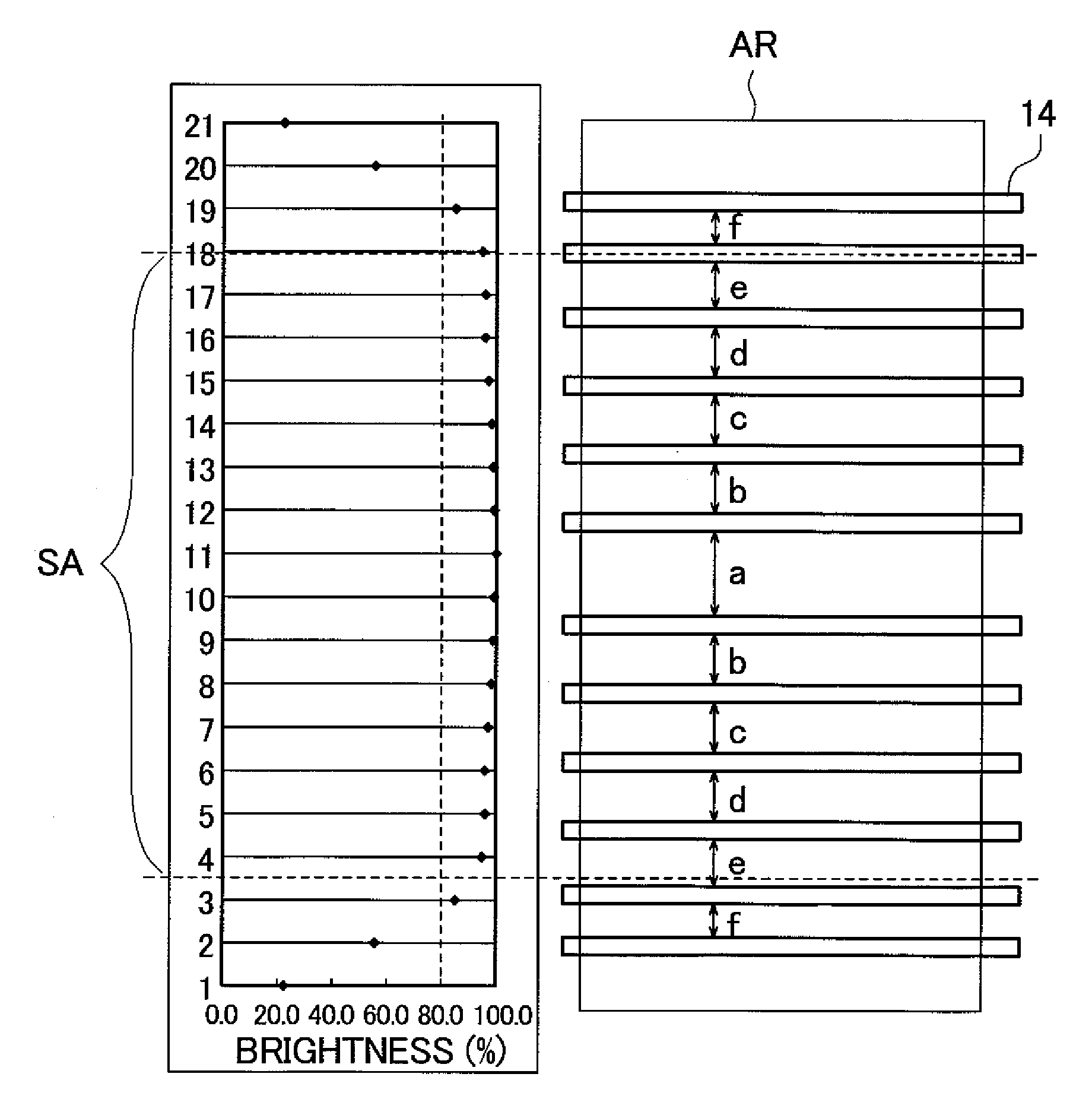
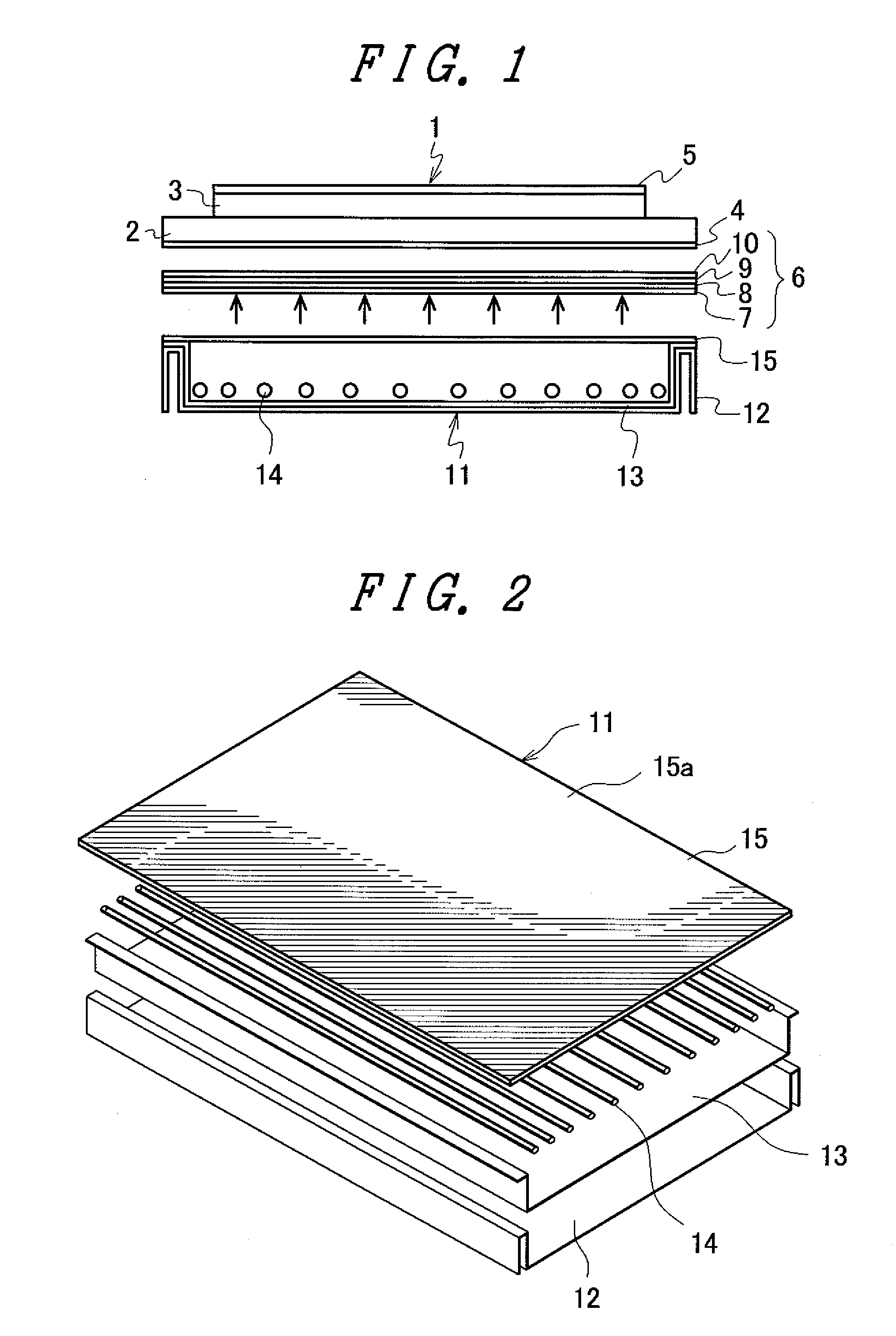
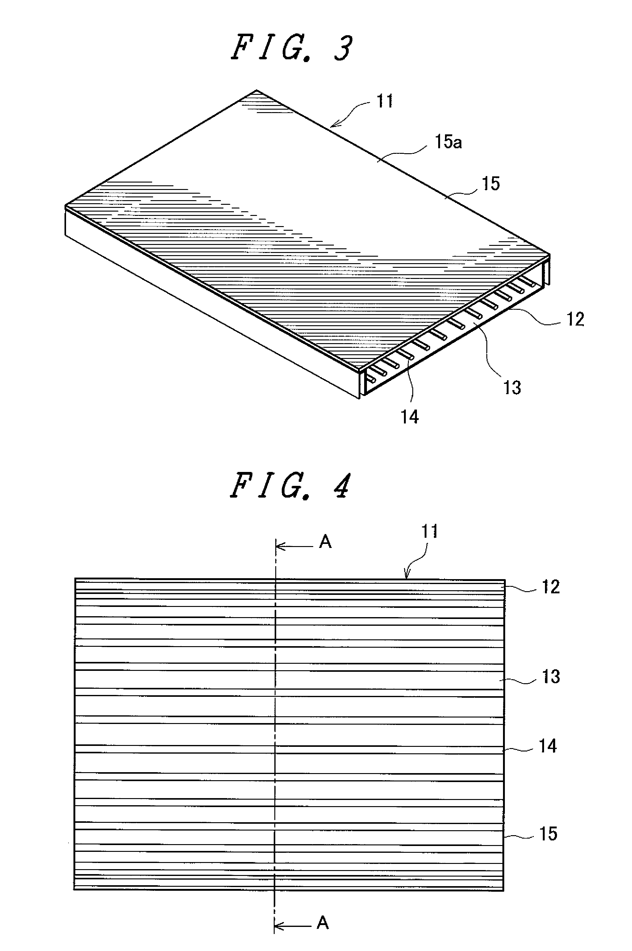
[0031]FIG. 1 is a longitudinal cross-sectional view of an essential part of the constitution of a liquid crystal display device according to one embodiment of the present invention. In FIG. 1, the liquid crystal display panel 1 is constituted of a first glass substrate 2 which is formed of a light-transmitting glass plate, a second glass substrate 3 which is formed of a light-transmitting glass plate, a liquid crystal layer which is sandwiched between the first and second glass substrates 2, 3, and electrodes or active elements and the like for forming pixels which are formed on both or one of inner surfaces of the first glass substrate 2 and the second glass substrate 3. Here, the first glass substrate 2 on which active elements such as thin film transistors (TFTs) are formed is referred to as an active-matrix substrate, a glass substrate which uses thin film transistors is also referred to as a TFT substrate, and the second glass substrate 3 on which color filters are formed is re...


PUM

PropertyMeasurementUnit
brightnessaaaaaaaaaa
thicknessaaaaaaaaaa
arrangement structureaaaaaaaaaa

Abstract

A liquid crystal display device includes a liquid crystal display panel and a backlight device which supplies light to a back surface of the liquid crystal display panel. The backlight device includes a diffusion plate, a plurality of cold cathode fluorescent lamps, and a reflection plate on which light is reflected. Assuming arrangement intervals of the plurality of cold cathode fluorescent lamps in the direction from a center portion to a peripheral portion as “a”, “b”, “c”, “d”, “e”, and “f” respectively, the plurality of cold cathode fluorescent lamps is arranged to satisfy the relationship of a>b≧c≧d≧e≧f. Such a liquid crystal display device can control the brightness distribution due to the arrangement of the cold cathode fluorescent lamps within the backlight device thus obtaining a high-quality image display without generating brightness irregularities.

Description

CROSS-REFERENCE TO RELATED APPLICATION[0001]The present application claims priority from Japanese application JP2008-097028 filed on Apr. 3, 2008, the content of which is hereby incorporated by reference into this application.BACKGROUND OF THE INVENTION[0002]1. Field of the Invention[0003]The present invention relates to a liquid crystal display device using a direct backlight device having cold cathode fluorescent lamps which is arranged on a back-surface side of a liquid crystal display panel and radiates light-source light to the liquid crystal display panel, and more particular to the arrangement structure of a plurality of cold cathode fluorescent lamps which is arranged in the inside of the backlight device.[0004]2. Description of the Related Art[0005]Recently, a liquid crystal display device has been popularly used as a display means for various information-terminal-use monitors including a personal computer, a mobile phone or a television receiver set or the like. In such a ...

Claims


Application Information

Patent Timeline
Patent Type & Authority Patents(United States)
IPC IPC(8): G02F1/1335G09F13/08G09F13/04
CPCG02F1/133604G02F1/133611
Inventor OTA, TAKAYUKI
Owner PANASONIC LIQUID CRYSTAL DISPLAY CO LTD
Why Eureka
Try Eureka