
Method and device for installing cable into cable guide tubing

a cable guide and cable technology, applied in special-purpose vessels, instruments, manufacturing tools, etc., can solve the problems of difficult connection, difficult completion of the connection, and difficulty in completing the connection, and achieve the effect of facilitating the introduction of cable into the duct and cost-effectiveness

Active Publication Date: 2012-02-21
DRAKA COMTEQ BV
View PDF22 Cites 30 Cited by
  • Summary
  • Abstract
  • Description
  • Claims
  • Application Information

AI Technical Summary

Benefits of technology

This method allows for the efficient and cost-effective installation of multiple microducts to the full length of the duct without high tensions or protrusions, ensuring consistent cable lengths and reducing installation difficulties.

Problems solved by technology

The present inventors have found that the use of compressed air (or other blowing technology) for installing a cable into a prefabricated duct is susceptible to a number of problems.
Undesirable cable tensions often exist when cables (e.g., microducts) of different lengths are present in the same duct.
This not only makes completing the connection more difficult but also can cause cable damage.
Furthermore, blowing cables into a duct in mutually different lengths leads to increased friction between the various cables.
This, of course, causes installation in the duct to become more difficult and, thus, less installation length can be achieved.

Method used


Image

  • Method and device for installing cable into cable guide tubing

Examples


example 1

Comparative

[0038]Seven microducts each having an external diameter of 7 millimeters (i.e., describing a “cable” as discussed herein) were simultaneously introduced into a duct having an internal diameter of 23 millimeters via a blowing method using equipment as disclosed in European Patent No. EP 0,292,037 (and its counterpart U.S. Pat. No. 4,934,662). The length of the duct was 500 meters. The cable (i.e., the seven microducts) did not reach the end of the duct; the cable was blown into the duct over a distance of only 16 meters.

example 2

Comparative

[0039]A cable consisting of four microducts each having an external diameter of 12 millimeters was introduced into a duct having an internal diameter of 33 millimeters via a blowing method. The length to be installed was 950 meters using equipment as disclosed in European Patent No. EP 0,292,037 (and its counterpart U.S. Pat. No. 4,934,662). The installation length that could be achieved was acceptable, but the operation was frequently found to be difficult. The required compressed air pressure was too high, introducing considerable risk of microduct implosion. In general, using high pushing pressure such as that required here can cause microduct damage.

example 3

Comparative

[0040]Using the method described in Examples 1 and 2, four sub-bundles of (i) six microducts each having an external diameter of 4 millimeters and (ii) being wound around a central stiffening element having a diameter of 4.2 millimeters were introduced into a duct having an internal diameter of 33 millimeters. A length of 950 millimeters was achieved, but the same problems described in Example 2 were encountered. Moreover, the field installation resulted in different lengths of the six sub-bundles within the duct. As noted, this leads to protrusion problems (e.g., buckling of the microduct sub-bundles) when the duct is opened to facilitate connection operations.


PUM

PropertyMeasurementUnit
oscillation angleaaaaaaaaaa
internal diameteraaaaaaaaaa

Abstract

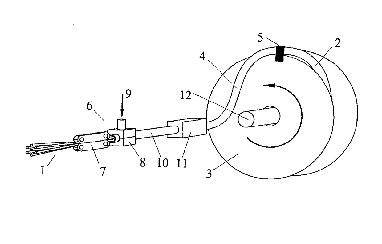
Disclosed is an improved method and apparatus for installing a cable into cable guide tubing and the like. The method typically includes rotating a reel of cable guide tubing at least 360° while, using compressed gas, feeding a cable, such as a plurality of microducts, into the cable guide tubing. The related apparatus includes a cable injection unit and a rotation coupling unit to facilitate the installation of cable (e.g., microducts) into the rotating cable guide tubing.

Description

CROSS-REFERENCE TO PRIORITY APPLICATION[0001]This application claims the benefit of pending Dutch Application No. 1032917 (filed Nov. 22, 2006, at the Netherlands Industrial Patent Office), which is hereby incorporated by reference in its entirety.FIELD OF THE INVENTION[0002]The present invention relates to an improved method and apparatus for installing or otherwise inserting a cable (e.g., microducts) into cable guide tubing (i.e., duct).BACKGROUND OF THE INVENTION[0003]Various methods for installing cables into tubes are known.[0004]For example, European Patent No. EP 0,292,037 (and its counterpart U.S. Pat. No. 4,934,662), recognize that compressed air flow passed through a duct exerts a drag force on a cable being introduced into the duct, thereby pulling the cable through the duct towards the duct outlet. U.S. Pat. No. 4,934,662 is hereby incorporated by reference in its entirety.[0005]U.S. Pat. No. 5,946,788 discloses a method for inserting a cable into tubular sheathing that...

Claims


Application Information

Patent Timeline
Patent Type & Authority Patents(United States)
IPC IPC(8): B65H59/00B23P19/04E21C29/16H02G1/08G02B6/44
CPCB65H51/16G02B6/4457G02B6/4485Y10T29/49838G02B6/4464G02B6/52
Inventor GRIFFIOEN, WILLEMGREVEN, WILLEMPOTHOF, THOMASVERSTEEG, PATRICK MENNOVAN T HUL, CORNELISVAN WINGERDEN, ARIE
Owner DRAKA COMTEQ BV
Learn More