Bag-on-valve assembly

a valve assembly and valve body technology, applied in the field of valve assembly of bags, can solve the problems of high cost of raw materials used to fabricate bags, brittleness of metal foil, and fragility of both the valve and the bag combination, and achieve the effect of high slow rate penetration resistance value and more puncture resistan

Active Publication Date: 2012-02-21
BEMIS COMPANY INC
View PDF11 Cites 4 Cited by
  • Summary
  • Abstract
  • Description
  • Claims
  • Application Information

AI Technical Summary

Benefits of technology

[0017]“Slow Rate Penetration Resistance” herein refers to the test which permits flexible thermoplastic webs to be characterized for slow rate penetration resistance to a driven probe. The test is performed at room temperature, by applying a biaxial stress at a single test velocity on the material until perforation occurs. The force, energy, and elongation to perforation ar

Problems solved by technology

Disadvantages of bag-on-valve systems include fragility of both the bag and bag/valve combination, and the cost of raw materials used to fabricate the bag.
However, metal foil is expensive and tends to be brittle.
Under press

Method used


Image

  • Bag-on-valve assembly
  • Bag-on-valve assembly

Examples


Embodiment Construction

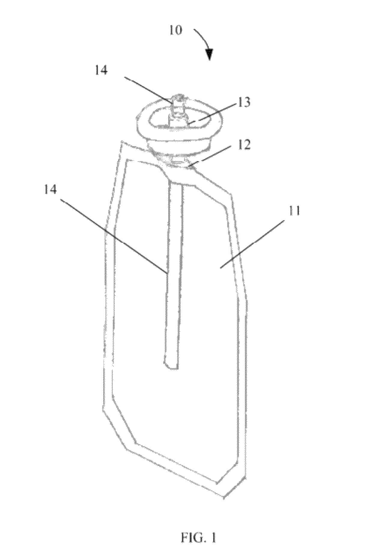
[0023]A preferred embodiment of the bag-on-valve assembly of the present invention is depicted in FIG. 1. The improved bag-on-valve assembly 10 includes a flexible bag 11 made of a thermoplastic multilayer film (see FIG. 2) which is affixed to valve stem 14. According to a preferred embodiment of the present invention, valve stem 14 may be attached to bag 11 by any conventional method known in the art which may include, but is not limited to, heat sealing, crimping and the use of an appropriate adhesive. Preferably, valve stem 14 is heat sealed to bag 11. As depicted, bag 11 is heat sealed directly to a valve stem at valve stem body 12 positioned below valve 13.

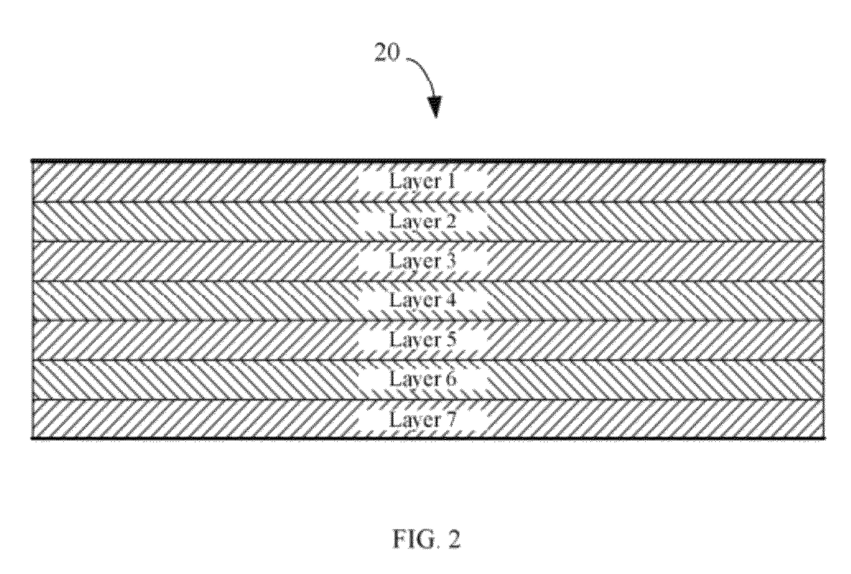
[0024]In FIG. 2 there is illustrated a preferred embodiment of a thermoplastic film structure for use as a flexible bag according to the present invention. As depicted, multilayer film structure 20 comprises seven layers (in sequential order of 1 through 7), respectively. It will be noted layer 1 is a heat sealable layer. It ...


PUM

PropertyMeasurementUnit
Lengthaaaaaaaaaa
Lengthaaaaaaaaaa
Thicknessaaaaaaaaaa

Abstract

The present invention is directed to a bag-on-valve assembly comprising a valve stem and a flexible bag which is affixed to the valve stem and encapsulates a portion of said valve stem therein. The bag comprises a sealable thermoplastic film which is free of foil and is adapted to have an Tensile Energy to Break value of at least 150 in*ft-lbs in both the machine direction and transverse directions.

Description

FIELD OF THE INVENTION[0001]The present invention relates generally to a bag-on-valve assembly, and more particularly to a bag-on-valve assembly including a flexible bag with improved film properties.BACKGROUND OF THE INVENTION[0002]Bag-on-valve systems are described in the prior art. For example, U.S. Pat. No. 3,823,849, assigned to Coster Technologie Speciali SPA, describes a system in which a flexible bag is sealed to the valve and valve housing of an aerosol valve. Likewise, U.S. Pat. No. 7,124,788, assigned to Precision Valve Corporation, describes a similar bag-on-valve arrangement, where the valve has two filling position. One is used to fill the bag with a product and the other position directs propellant into the aerosol container outside the bag.[0003]In a bag-on-valve system, the product to be dispensed is filled into the inside of the bag and a liquefied or compressed gas propellant is filled into the aerosol container outside the bag. When the aerosol valve is actuated,...

Claims


Application Information

Patent Timeline
IPC IPC(8): B32B1/02B32B1/08
CPCB32B27/08B32B27/32B32B27/327B32B27/34B32B27/306Y10T428/139B32B2250/24B32B2270/00B32B2307/31B32B2307/7244B32B2307/7246B32B2439/00B32B2439/46Y10T428/13Y10T428/1359Y10T428/1352Y10T428/1334Y10T428/1303
Inventor TAYLOR, NATHAN EDWARDNETTEKOVEN, JOHN KENNETH
Owner BEMIS COMPANY INC
Why Eureka
Try Eureka