On-load tap changer with an energy storage mechanism

a technology of energy storage mechanism and tap changer, which is applied in the direction of electric switches, switch power arrangements, electrical appliances, etc., can solve the problems of limited mechanical fatigue strength of employed tension springs, and the inability of the tension spring to have unlimited mechanical fatigue strength, and the disadvantage of known force-storing units

Active Publication Date: 2012-02-21
MASCHFAB REINHAUSEN GEBR SCHEUBECK GMBH & CO KG
View PDF9 Cites 8 Cited by
  • Summary
  • Abstract
  • Description
  • Claims
  • Application Information

AI Technical Summary

Benefits of technology

[0012]In addition to the intended almost unlimited mechanical fatigue strength of the compression springs employed, the breakage of which is practically impossible, the advantage of the invention lies in the fact that the amount of force of the force-storing unit can be continuously adjusted due to the use of a threaded adjustable pull rod. As a result, it easily becomes possible to adjust the force-storing unit in advance to a wide variety of types of load tap changers and to adjust the force-storing unit in terms of the force released after triggering. The force-storing unit according to the invention is usable with a wide variety of on-load tap changers; it can be used both with equipment switching under oil using mechanical tap contacts and also with those having vacuum switching cells.
lies in the fact that the amount of force of the force-storing unit can be continuously adjusted due to the use of a threaded adjustable pull rod. As a result, it easily becomes possible to adjust the force-storing unit in advance to a wide variety of types of load tap changers and to adjust the force-storing unit in terms of the force released after triggering. The force-storing unit according to the invention is usable with a wide variety of on-load tap changers; it can be used both with equipment switching under oil using mechanical tap contacts and also with those having vacuum switching cells.

Problems solved by technology

Nevertheless, the tension springs used do not have unlimited mechanical fatigue strength but must be replaced after a predetermined operating life or permissible number of operations for reason of safety.
Due to the high reliability of the vacuum-type switching cells now available and used, and the overall advantages of vacuum switching technology, it is now possible, however, to increase the maintenance intervals for on-load tap changers such that the limited mechanical fatigue strength of the employed tension springs has increasingly proven to be a disadvantage for the known force-storing units.

Method used


Image

  • On-load tap changer with an energy storage mechanism
  • On-load tap changer with an energy storage mechanism

Examples


Embodiment Construction

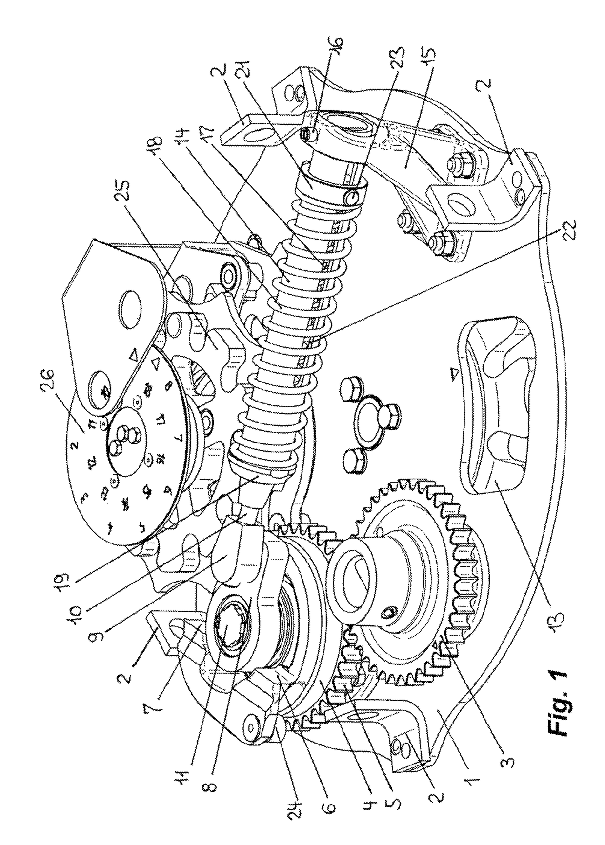
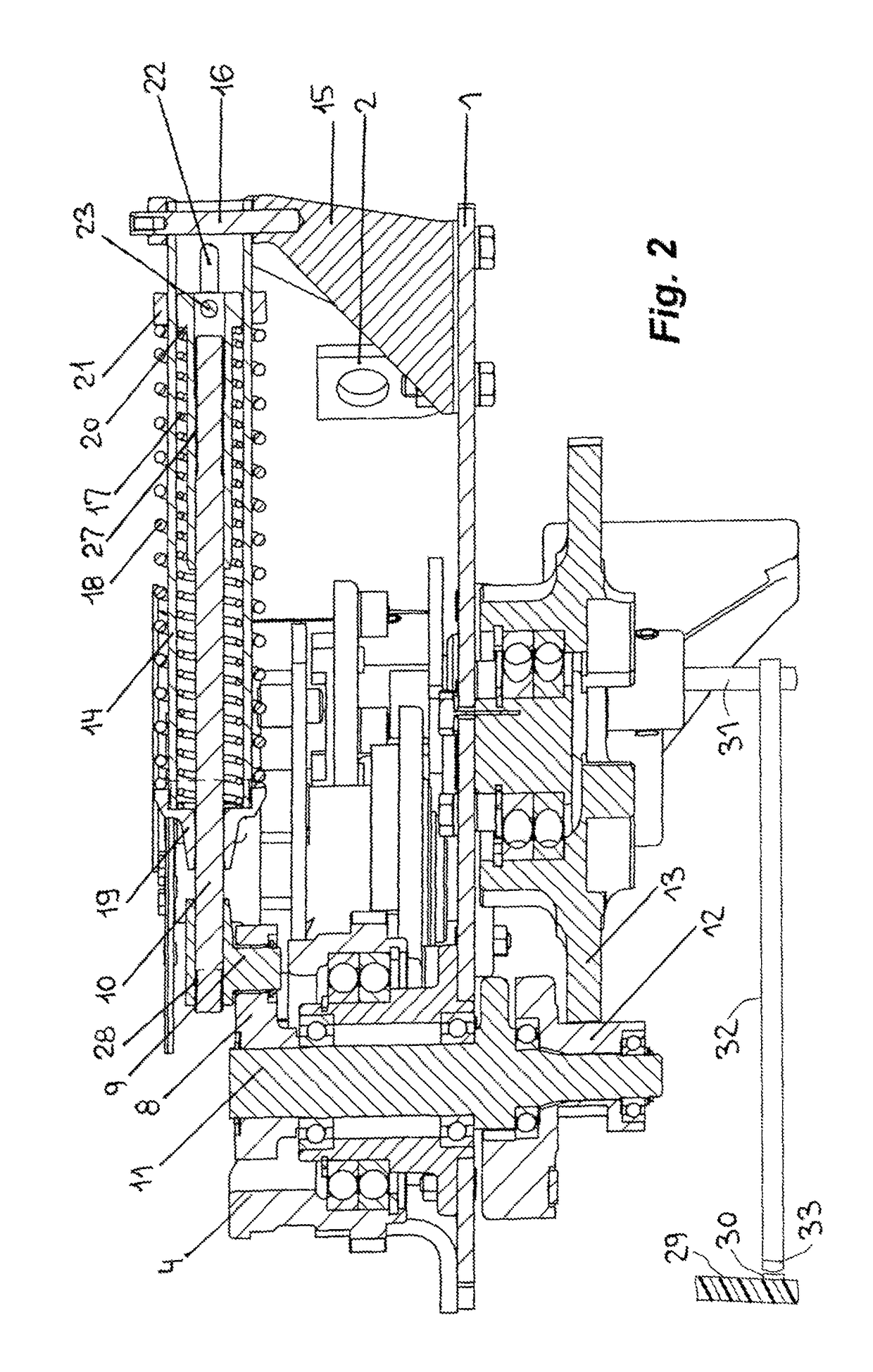
[0016]FIG. 1 will be described in detail first. Shown is a base plate 1 on which the entire force-storing unit and drive arrangement for actuating the on-load tap changer is mounted and which in turn is mounted normally at an upper end of a dielectric cylinder 29 (FIG. 2 only) carrying a multiplicity of contacts 30 of which only one is shown. The base plate 1 has support brackets 2. A gear wheel 3 is shown that is connected to an unillustrated drive-motor shaft. The gear wheel 3 drives a drive element 4 by means of its gear teeth 5. The drive element 4 in turn has two symmetrical catches 6 and 7 that coact with a drive crank 8. This will be explained in more detail later. A head 9 of a pull rod 10 is pivoted on the drive crank 8. The pull rod 10 is connected to additional parts of the force-storing unit according to the invention that will be explained in detail further below. The drive crank 8 is attached to an operating shaft 11 that passes vertically downward completely through t...


PUM


Abstract

The invention relates to an on-load tap changer having an energy storage mechanism for changing over, without any interruptions, between different winding taps of a tap-changing transformer on load. According to the invention, the energy storage mechanism has one or more compression springs, which are tensioned at the beginning of a changeover operation. In comparison with the tensile springs used to date with such energy storage mechanisms, the compression springs have markedly greater long-term strength.

Description

CROSS REFERENCE TO RELATED APPLICATIONS[0001]This application is the US national stage of PCT application PCT / EP2006 / 010580, filed 4 Nov. 2006, published 30 Aug. 2007 as WO 2007 / 095978, and claiming the priority of German patent application 102006008338.5 itself filed 23 Feb. 2006, whose entire disclosures are herewith incorporated by reference.FIELD OF THE INVENTION[0002]The invention relates to an on-load tap changer having a force-storing unit for the uninterrupted switching between different winding taps of a tapped transformer under load.BACKGROUND OF THE INVENTION[0003]An on-load tap changer of this type along with an associated force-storing unit is known from publication of the applicant “On-load tap Changer VACUTAP® VV Operating Instructions,” imprint BA164 / 03de. This on-load tap changer combines the function of a selector for the no-load preselection of the tap to which the changeover is to be made, as well as a load transfer switch for the actual switching.[0004]The force...

Claims


Application Information

Patent Timeline
Patent Type & Authority Patents(United States)
IPC IPC(8): H01H19/00H01H21/00
CPCH01H9/0027H01H3/30H01H9/00
Inventor ALBRECHT, WOLFGANGHUBER, THOMAS M.
Owner MASCHFAB REINHAUSEN GEBR SCHEUBECK GMBH & CO KG
Why Eureka
Try Eureka