Semiconductor device and photomask
a technology of semiconductor devices and photomasks, applied in semiconductor devices, electrical devices, transistors, etc., to achieve the effect of suppressing the generation of opening defects
- Summary
- Abstract
- Description
- Claims
- Application Information
AI Technical Summary
Benefits of technology
Problems solved by technology
Method used
Image
Examples
first embodiment
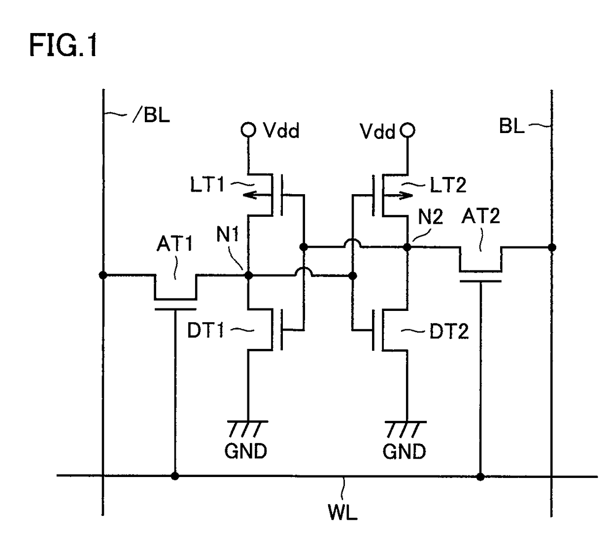
[0046]Referring to FIG. 1, an SRAM is a volatile semiconductor memory device, and a memory cell of the SRAM is a full CMOS (Complementary Metal Oxide Semiconductor) type memory cell.
[0047]In the SRAM, the memory cell is disposed in each of intersections of complementary data lines (bit lines) BL and / BL and word lines WL. Complementary data lines (bit lines) BL and / BL and word lines WL are disposed in a matrix shape. The memory cell includes a flip-flop circuit provided with a pair of inverter circuits and two access transistors AT1 and AT2. Cross-coupled two storage nodes N1 and N2 are formed to obtain a bistable state of (High, Low) or (Low, High) by the flip-flop circuit. The memory cell continuously retains the bistable state as long as a predetermined power supply voltage is applied to the memory cell.
[0048]Each of access transistors AT1 and AT2 includes an n-channel MOS transistor (hereinafter referred to as nMOS transistor). One of a source and a drain of access transistor A...
second embodiment
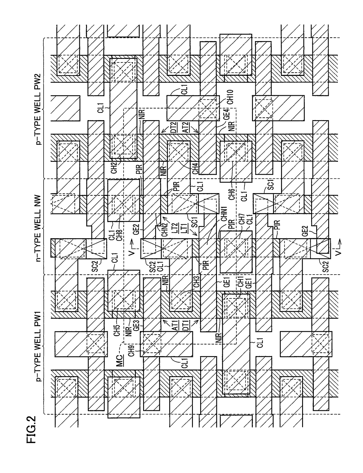
[0112]Referring to FIG. 21, a configuration of a second embodiment differs from the configuration of the first embodiment in that sidewall E2 is intersected with sidewall E1 while inclined relative to sidewall E1. Specifically, sidewall E2 is inclined so as to be retreated toward the side of sidewall E4 with respect to virtual extended line E1a of sidewall E1 as sidewall E2 is away from channel formation region CHN1, and sidewall E2 is intersected with virtual extended line E1a of sidewall E1 at an angle θ1.
[0113]In the planar view, the center line (line C2-C2) of line width D1 in the portion that shared contact hole SC1 of gate electrode layer GE1 reaches is shifted toward the side of sidewall E4 with respect to the center line (line C1-C1) of line width D2 in the portion located on channel formation region CHN1 of gate electrode layer GE1. The center line (line C2-C2) of line width D1 is inclined relative to the center line (line C1-C1) of line width D2. Line width D1 and line wid...
third embodiment
[0124]In the first and second embodiments, sidewall E4 in the portion that shared contact hole SC1 (or SC2) of gate electrode layer GE1 (or GE2) reaches and sidewall E3 in the portion located on channel formation region CHN1 (or CHN2) of gate electrode layer GE1 (or GE2) are located on the same straight line. Moreover, the present invention can also be applied to the case in which sidewall E4 and sidewall E3 are located on different straight lines. Therefore, third and fourth embodiments will be described for the case in which sidewall E4 and sidewall E3 are located on different straight lines.
[0125]Referring to FIG. 23, a configuration of the third embodiment differs from the configuration of the first embodiment in that sidewall E4 is located on a straight line different from that of sidewall E3.
[0126]In the third embodiment, sidewall E4 in the portion that shared contact hole SC1 of gate electrode layer GE1 reaches is substantially extended in parallel with sidewall E3 in the por...
PUM
 Abstract
Description
Claims
Application Information
 - R&D
- Intellectual Property
- Life Sciences
- Materials
- Tech Scout
- Unparalleled Data Quality
- Higher Quality Content
- 60% Fewer Hallucinations
Browse by: Latest US Patents, China's latest patents, Technical Efficacy Thesaurus, Application Domain, Technology Topic, Popular Technical Reports.
© 2025 PatSnap. All rights reserved.Legal|Privacy policy|Modern Slavery Act Transparency Statement|Sitemap|About US| Contact US: help@patsnap.com


