Boundary transition region stitching for tessellation

a boundary transition and region technology, applied in the field of patch tessellation, can solve the problems of triangle mesh not being smooth-varying, similar size of triangle mesh, and the way the stitching of vertices within the boundary transition region is done, and achieves the effect of high quality

Active Publication Date: 2012-02-21
NVIDIA CORP
View PDF19 Cites 41 Cited by
  • Summary
  • Abstract
  • Description
  • Claims
  • Application Information

AI Technical Summary

Benefits of technology

[0006]A system and method for tessellating a patch in three-dimensional space and stitching graphics primitives to define a topology of a boundary transition region of the patch. The topology includes high quality graphics primitives that form a smoothly-varying triangle mesh for various combinations of tessellation levels of detail. The triangle mesh topology varies smoothly as the tessellation levels of detail change continuously over time and a

Problems solved by technology

Current mechanisms for stitching vertices within boundary transition regions do not necessarily produce graphics primitives that are similar in size, particularly when tessellation levels of detail on eith

Method used


Image

  • Boundary transition region stitching for tessellation
  • Boundary transition region stitching for tessellation
  • Boundary transition region stitching for tessellation

Examples


Embodiment Construction

[0023]In the following description, numerous specific details are set forth to provide a more thorough understanding of the present invention. However, it will be apparent to one of skill in the art that the present invention may be practiced without one or more of these specific details. In other instances, well-known features have not been described in order to avoid obscuring the present invention.

System Overview

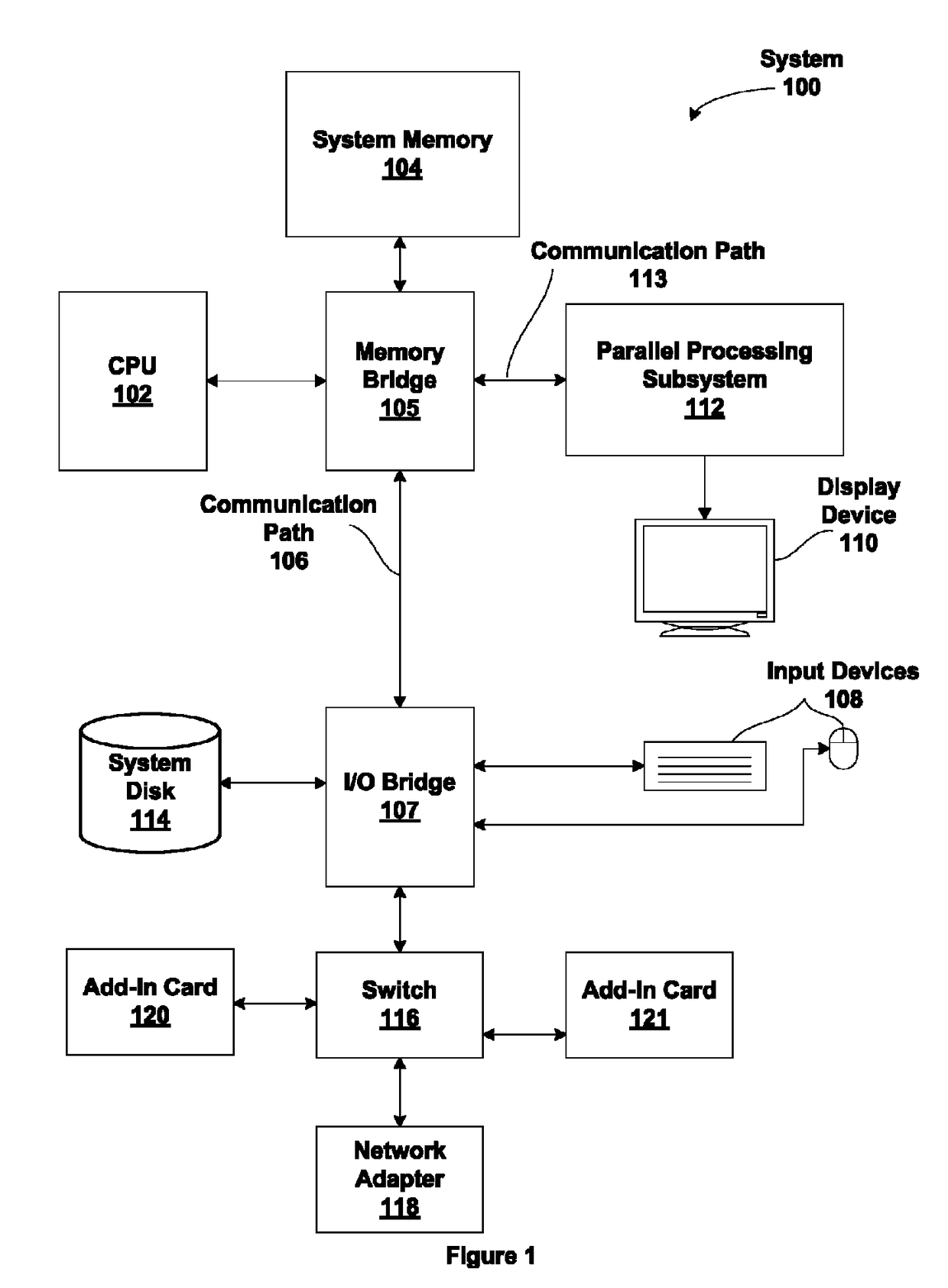
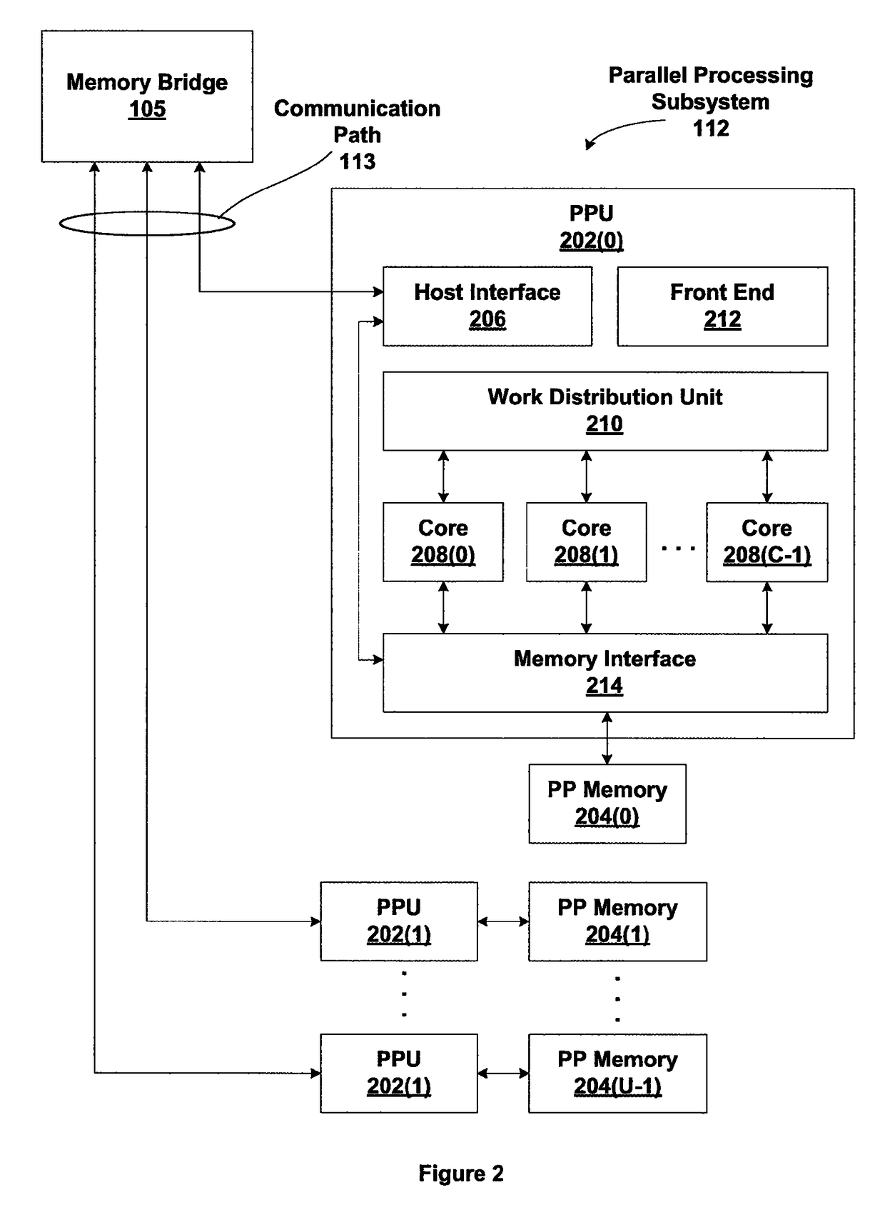
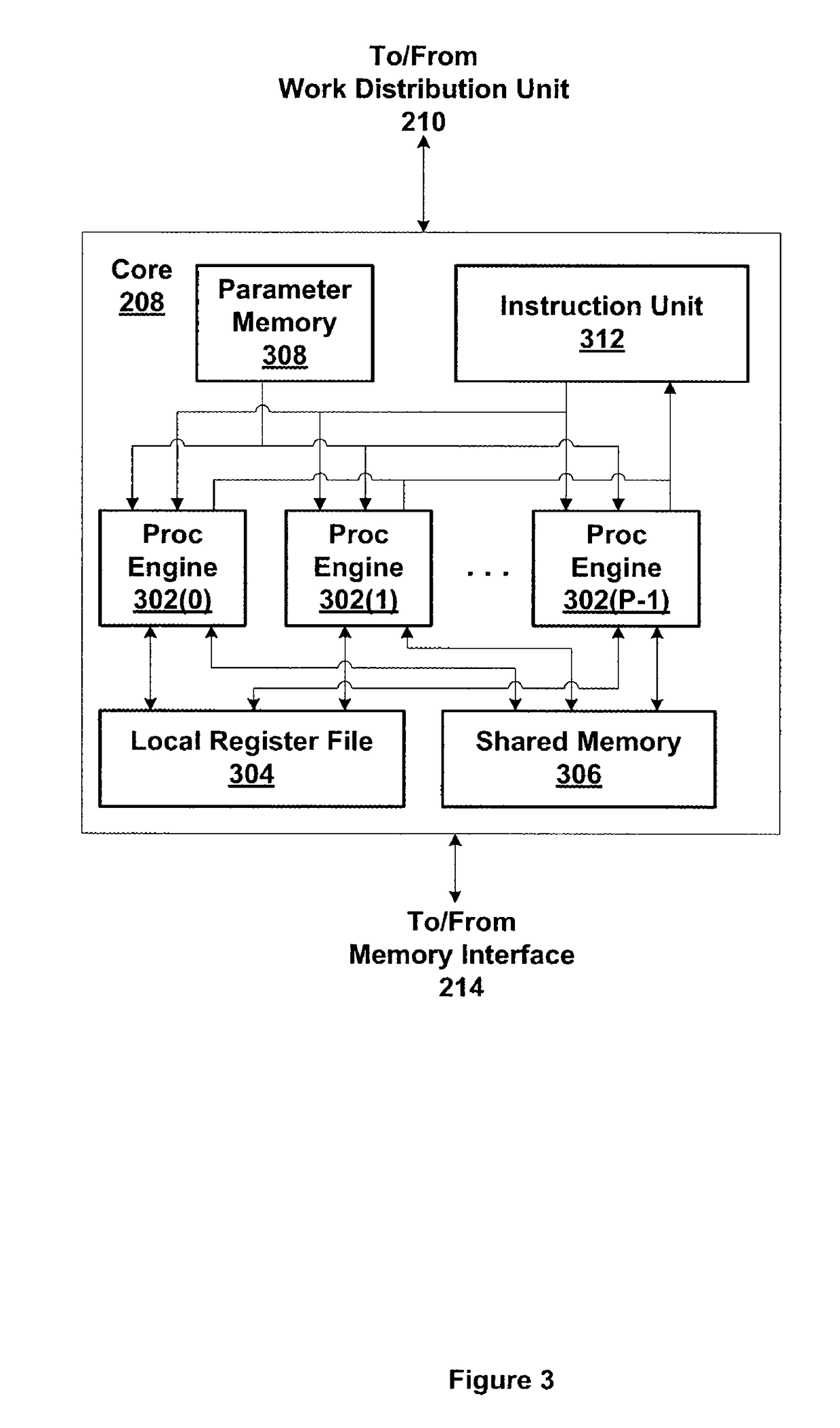
[0024]FIG. 1 is a block diagram illustrating a computer system 100 configured to implement one or more aspects of the present invention. Computer system 100 includes a central processing unit (CPU) 102 and a system memory 104 communicating via a bus path that may include a memory bridge 105. Memory bridge 105, which may be, e.g., a Northbridge chip, is connected via a bus or other communication path 106 (e.g., a HyperTransport link) to an I / O (input / output) bridge 107. I / O bridge 107, which may be, e.g., a Southbridge chip, receives user input from one or more user input ...


PUM


Abstract

A system and method for stitching a boundary transition region of a patch produces a graphics primitive topology for the boundary transition region of the patch. A first number of vertices is computed for an inside edge of the boundary transition region using a first tessellation level of detail (LOD) of the inside edge. A second number of vertices is computed for an outside edge of the boundary transition region using a second tessellation LOD of the outside edge. A portion of the first number of vertices and the second number of vertices are merged based on a stitching pattern to produce a set of vertices for the boundary transition region. The set of vertices is stitched to produce an ordered list representing the graphics primitive topology.

Description

BACKGROUND OF THE INVENTION[0001]1. Field of the Invention[0002]The present invention generally relates to tessellation of patches in three-dimensional space to produce graphics primitives and more specifically to a system and method for stitching a boundary transition region on the edges of a patch.[0003]2. Description of the Related Art[0004]Surfaces in three-dimensional space are typically subdivided into patches for processing in order to produce an image. Conventional techniques define boundary transition regions between patches where the level of tessellation may vary. Current mechanisms for stitching vertices within boundary transition regions do not necessarily produce graphics primitives that are similar in size, particularly when tessellation levels of detail on either size of the transition region differ greatly. Similarly sized graphics primitives produce better quality images when the graphics primitives are rendered. Additionally, similarly sized graphics primitives pr...

Claims


Application Information

Patent Timeline
IPC IPC(8): G06T17/20G06T17/00
CPCG06T17/20
Inventor LEGAKIS, JUSTIN S.MORETON, HENRY PACKARD
Owner NVIDIA CORP
Why Eureka
Try Eureka