
Image processing method and apparatus, digital camera, and recording medium recording image processing program

a technology of image processing and image processing program, which is applied in the field of preprocessing technology for correcting distortions of photographed images, can solve the problems of difficult reading, object cannot be recognized, and pictures of train schedules and posters may be distorted depending on the situation, so as to achieve easy selection of optimal rectangles, high precision, and high speed

Active Publication Date: 2012-02-21
RICOH KK
View PDF11 Cites 14 Cited by
  • Summary
  • Abstract
  • Description
  • Claims
  • Application Information

AI Technical Summary

Benefits of technology

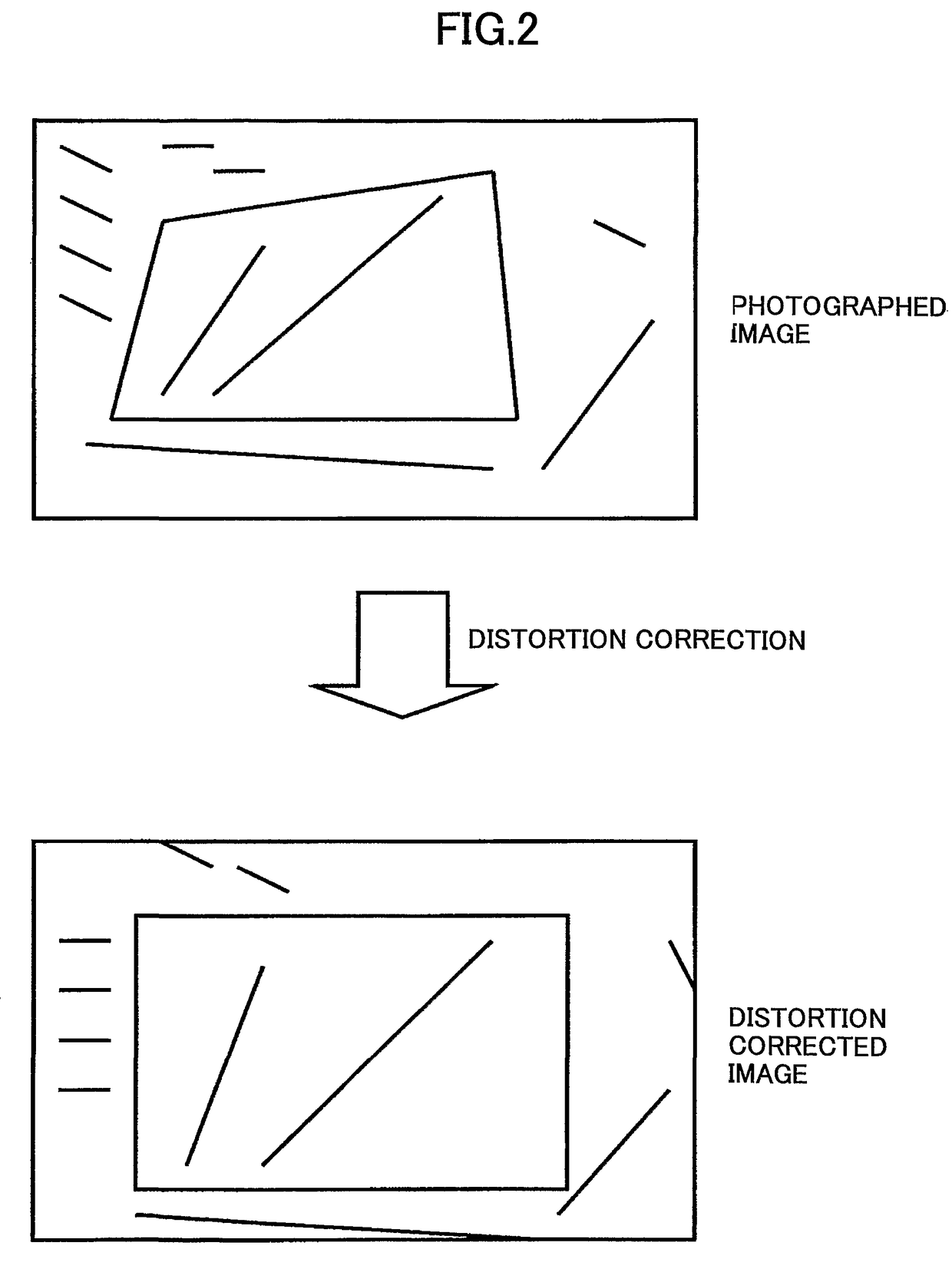
[0022]According to the present invention, a quadrangle can be recognized from a photographed image, and the recognized quadrangle can be transformed into an image that appears to have been taken from the front, with high precision and high speed.
[0023]According to the present invention, in using a digital camera, etc., when a plurality of shapes, e.g., rectangles, extracted from a photographed image are superposed on an image displayed for the user to select a desired rectangle, the user can easily select the optimal rectangle. Moreover, when a desired shape is not extracted, the user can modify an extracted shape to obtain the desired shape, without taking a photograph of the object again.

Problems solved by technology

However, photographed train schedules and posters may be distorted depending on the position from which the photograph is taken.
Such distorted posters are difficult to read, and therefore, the photographed images are not preferable.
Thus, when the object is not positioned in the middle of the image, i.e., when four sides to be recognized are not positioned in four directions from the center of the image, the object cannot be recognized.
Moreover, because Hough transformation, etc., is performed for detecting straight lines, the process takes extensive time.
The voting algorithm of the Hough transformation particularly requires an enormous amount of time.
The technology disclosed in Patent Document 2 attempts to enhance process speed by restricting the tilt of candidate straight lines in an X axis direction to 45°≦θ≦135°, and the tilt of candidate straight lines in a Y axis direction to 135°≦θ≦225°; however, the speed cannot be enhanced sufficiently.
Therefore, it is difficult to distinguish the rectangles.
Moreover, the camera cannot know the user's intention, and therefore, the rectangle desired by the user may not always be included among automatically extracted rectangles.
However, the conventional technology only allows the user to make a selection among the extracted rectangles.
If the desired rectangle is not included, the user has to take the trouble of photographing the object again.
Further, if the object has been taken from a moving vehicle, and the desired rectangle is not included among extracted rectangles, the user may not be able to photograph the object again.

Method used


Image

  • Image processing method and apparatus, digital camera, and recording medium recording image processing program
  • Image processing method and apparatus, digital camera, and recording medium recording image processing program
  • Image processing method and apparatus, digital camera, and recording medium recording image processing program

Examples


first embodiment

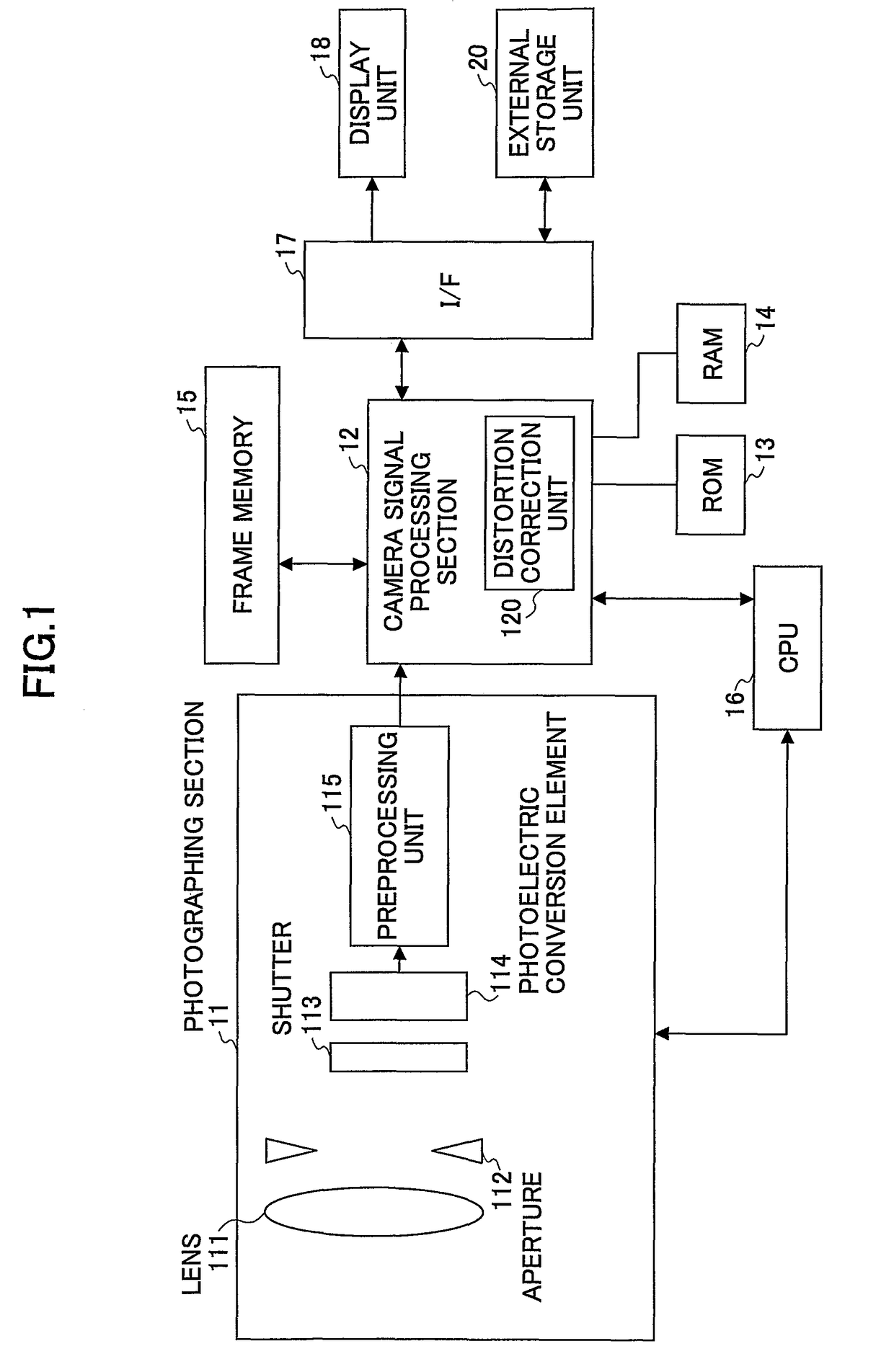
[0082]FIG. 1 is a block diagram of a digital camera including an image processing function according to the present invention. As shown in FIG. 1, a photographing section 11 includes a lens 111; an aperture 112, a shutter 113, a photoelectric conversion element 114, and a preprocessing unit 115. By operating the shutter 113, the photoelectric conversion element 114 receives an object light through the lens 111 and the aperture 112, and the object light is converted into analog image signals. An example of the photoelectric conversion element 114 is a CCD (charge-coupled device). The preprocessing unit 115 includes a preamplifier, an analog signal processing unit such as an AGC (automatic gain control), and an A / D conversion unit. The preprocessing unit 115 performs preprocesses such as amplifying / clamping on the analog image signals received from the photoelectric conversion element 114, and then converts the analog image signals into digital image signals.

[0083]The digital signals ...

second embodiment

[0162]More detailed descriptions are given below. FIG. 18 is a block diagram of a digital camera including an image processing function according to the present invention. As shown in FIG. 18, a photographing section 11 includes a lens 111, an aperture 112, a shutter 113, a photoelectric conversion element 114, and a preprocessing unit 115. By operating the shutter 113, the photoelectric conversion element 114 receives an object light through the lens 111 and the aperture 112, and the object light is converted into analog image signals. An example of the photoelectric conversion element 114 is a CCD charge-coupled device). The preprocessing unit 115 includes a preamplifier, an analog signal processing unit such as an AGC (automatic gain control), and an A / D conversion unit. The preprocessing unit 115 performs preprocesses such as amplifying / clamping on the analog image signals received from the photoelectric conversion element 114, and then converts the analog image signals into dig...

third embodiment

[0179]FIG. 22 is a flowchart of a superposed image creation method (part 1) according to a The process shown in FIG. 22 is performed for all pixels of the candidate quadrangles and the input image (RGB 256 shades).

[0180]Coordinates and a pixel value (Vr, Vg, Vb) of a pixel of an input image are input (step 301). Vr represents a pixel value for red (R), Vg represents a pixel value for green (G), and Vb represents a pixel value for blue (B). One candidate quadrangle is input (step 302). In this example, it is assumed that the first candidate quadrangle 2080 is input. Each pixel of the input image is considered as a target pixel, and the following process is performed on a target pixel.

[0181]The superposed image creating unit 202 determines whether a target pixel is on the perimeter of the quadrangle (step 303). A pixel on the perimeter of a quadrangle is defined as a pixel on a side of the quadrangle formed by four vertexes extracted by the quadrangle extracting unit 201 being connec...


PUM


Abstract

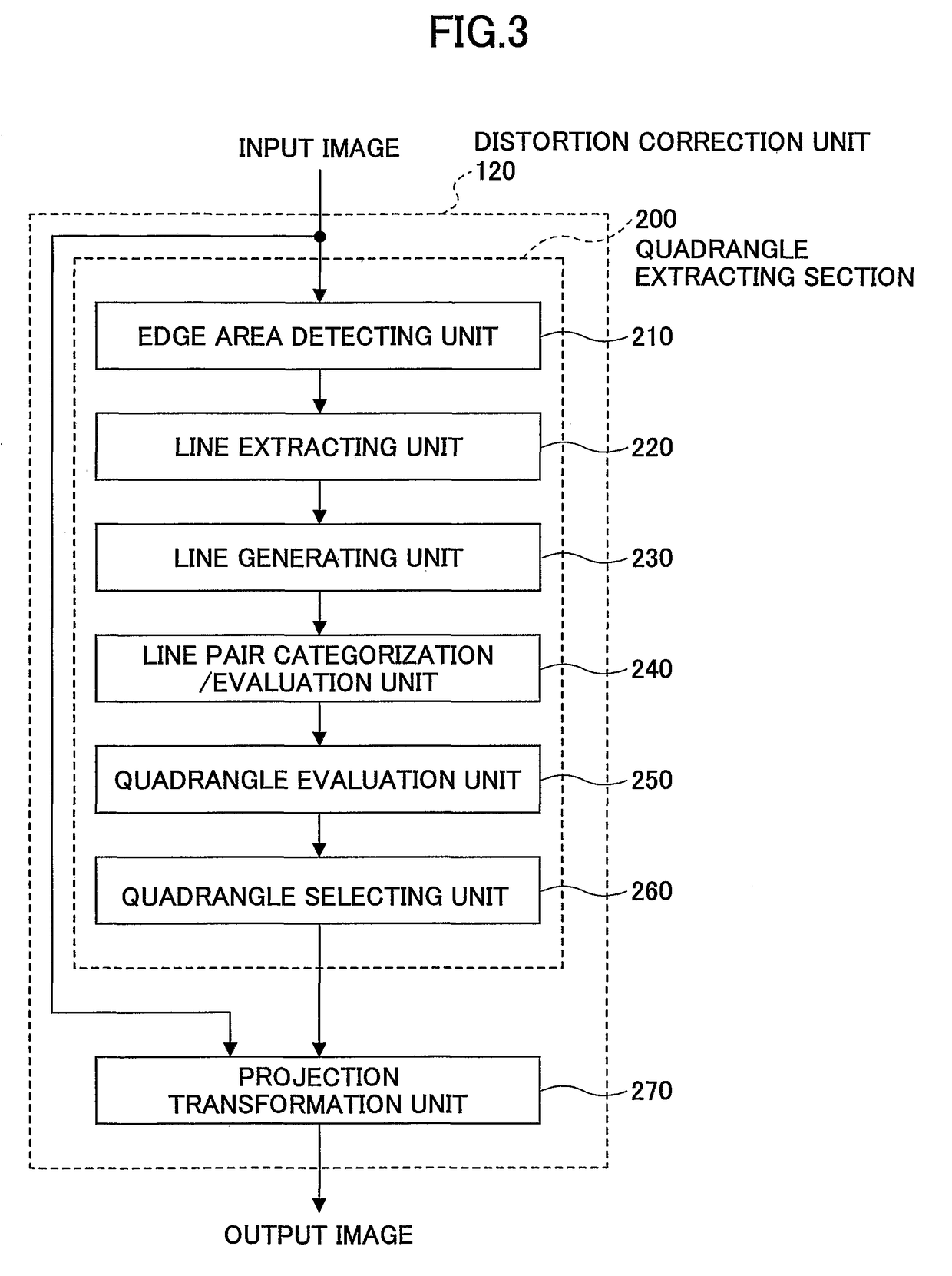
A technology for recognizing one or more quadrangles from an input image is disclosed. Edge areas are detected from the input image, lines corresponding to the edge areas are extracted, a line pair selected from the extracted lines is categorized according to a positional relationship between two lines included in the line pair, a line pair evaluation value is calculated for the line pair, a combination of two line pairs is selected, a quadrangle is generated from four lines included in the two line pairs selected, a quadrangle evaluation value is calculated for the quadrangle based on the categories and the line pair evaluation values of the two line pairs forming the quadrangle, and a quadrangle is selected based on the calculated quadrangle evaluation value.

Description

TECHNICAL FIELD[0001]The present invention relates to a preprocessing technology for correcting distortions of photographed images, and more particularly to an image processing method and apparatus, a digital camera having functions thereof, and a recording medium recording an image processing program for recognizing a quadrangle from an input image.[0002]Moreover, the present invention relates to an image processing method and apparatus, a digital camera having functions thereof, and a recording medium recording an image processing program for extracting a shape such as a quadrangle from a photographed image, and displaying an image including a highlighted shape area.BACKGROUND ART[0003]In recent years and continuing, digital cameras are becoming widely popular, and are being used not only for photographing scenery or people, but also for photographing train schedules, posters, bulletin boards, etc., instead of taking notes. However, photographed train schedules and posters may be ...

Claims


Application Information

Patent Timeline
Patent Type & Authority Patents(United States)
IPC IPC(8): H04N5/235
CPCG06T5/006G06T7/60H04N5/2621H04N5/2628G06T7/12
Inventor MARUYAMA, GOAOKI, SHIN
Owner RICOH KK
Learn More