Device for reducing the power demand for the propulsion of a ship

a technology for propulsion and power demand, applied in the direction of floating buildings, propulsive elements, water-acting propulsive elements, etc., can solve the problems of not being suitable for all propeller types and being suitable for fixed propellers, so as to improve the flow against the propeller, reduce the power demand of the propulsion of the ship, and improve the effect of efficiency

Inactive Publication Date: 2012-02-28
BECKER MARINE SYST
View PDF51 Cites 10 Cited by
  • Summary
  • Abstract
  • Description
  • Claims
  • Application Information

AI Technical Summary

Benefits of technology

[0007]It is the object of the present invention to create a device that serves to reduce the power demand for the propulsion of a ship. Furthermore, an improvement in the efficiency, and matching of the fins or hydrofoils to the flow are to be achieved. Moreover, the flow against the propeller is to be improved.
[0009]With a device constructed in this manner it is possible to reduce the power demand for the propulsion of a ship. The possible gain increases as the extent of thrust loading on the propeller increases. The device is particularly suitable for slow, broad-built ships, such as tankers, bulk transports and tugs, and also for not-very-fast ships of any type. The device itself is affixed to the hull so that it is upstream of the propeller of the ship, with said device comprising the two functional elements of fore-nozzle and fins or hydrofoils.
[0010]In this arrangement the effective principle of the fore-nozzle consists of increasing the speed of the flow against the propeller in areas where the main stream is very high, and of decreasing the flow against the propeller in areas where the main stream is low, wherein the nozzle itself generates thrust, while the effective principle of the fins or hydrofoils arranged within the fore-nozzle consists of generating a pre-swirl, wherein both functional elements target different sources of losses, namely the fore-nozzle aims at a reduction in the effective thrust loading, and the fins or hydrofoils target a reduction in the swirl losses in the propeller stream. Both effects result in an increase in the efficiency of the propulsion system.
[0011]As a result of the device being affixed as closely as possible upstream of the propeller, the best-possible effect is achieved, even in different load cases.

Problems solved by technology

The nozzle presented in the above-mentioned printed publication thus does not accelerate the flow in its region, and is not suitable for all propeller types, in particular it is not suitable for fixed propellers.

Method used


Image

  • Device for reducing the power demand for the propulsion of a ship
  • Device for reducing the power demand for the propulsion of a ship
  • Device for reducing the power demand for the propulsion of a ship

Examples


Embodiment Construction

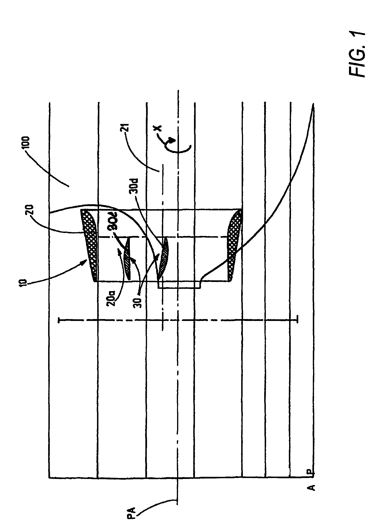
[0033]According to FIG. 1, in the device 10 according to the invention, a fore-nozzle 20 of a cylindrical shape or some other shape or cross-section is provided directly upstream of the propeller (not shown in the drawing) of a hull 100, which fore-nozzle 20 if affixed to the hull. In the interior space 20a of the fore-nozzle 20, fins or hydrofoils 30 are arranged. The fore-nozzle 20 is arranged on the hull so as to be rotationally symmetrical with its axis 21 shifted upwards.

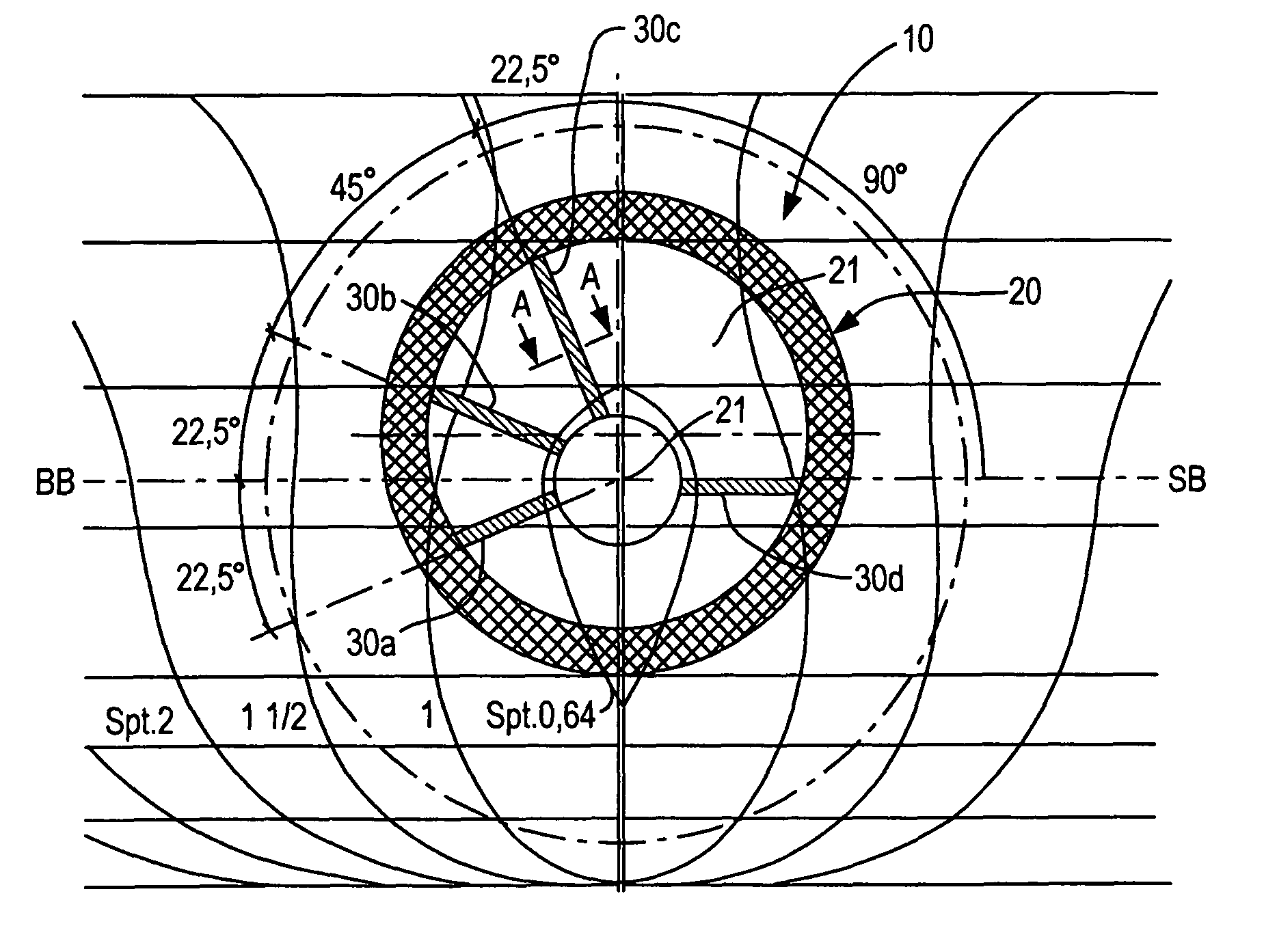
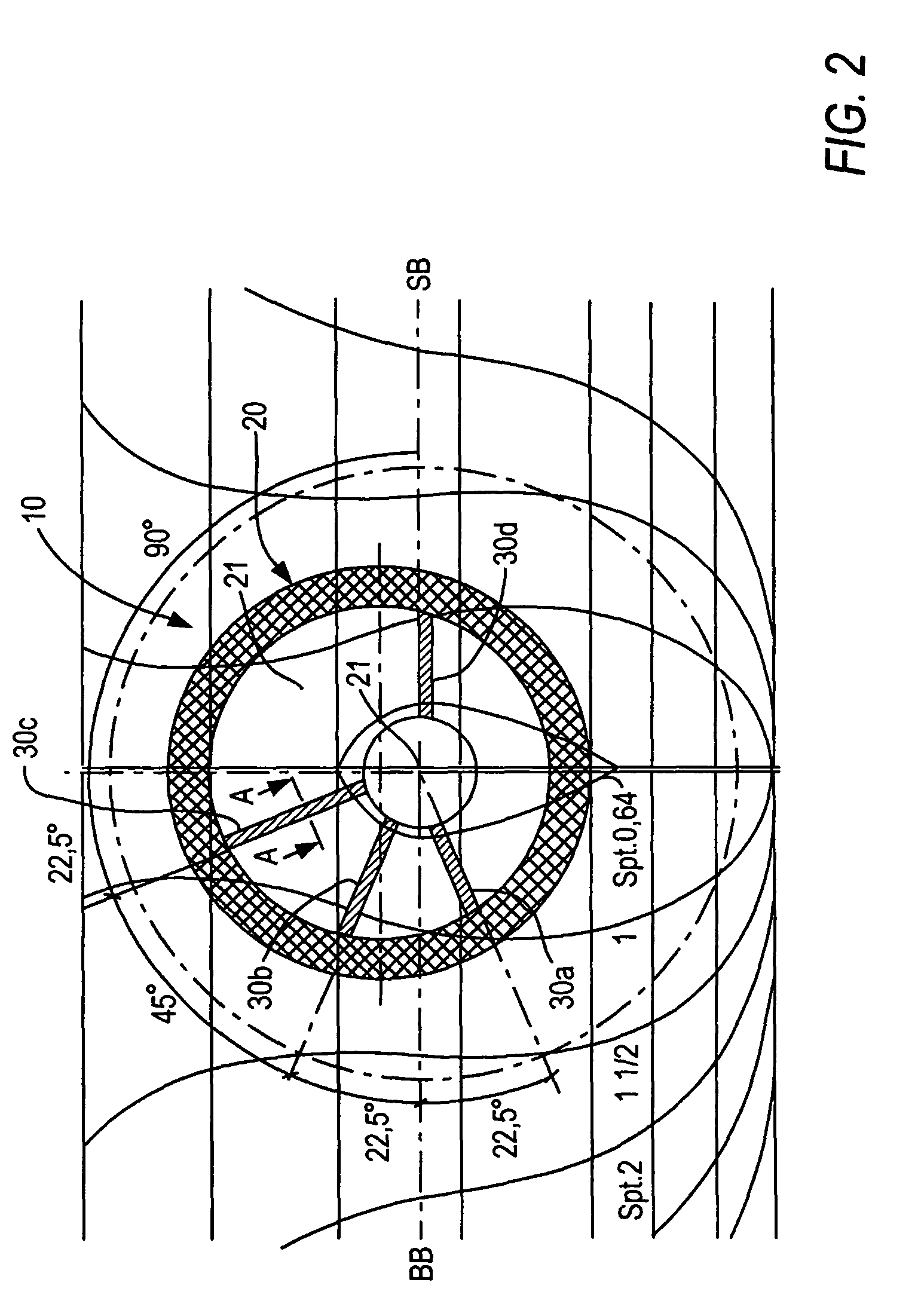
[0034]In the exemplary embodiment shown in FIG. 2, four fins or hydrofoils 30a, 30b, 30c, 30d with different fin lengths or hydrofoil lengths are arranged in the interior space 20a of the fore-nozzle 20. These four fins or hydrofoils are arranged asymmetrically within the fore-nozzle and radially to the propeller axis PA. In this arrangement the fins or hydrofoils 30a, 30b, 30c, 30d connect the fore-nozzle 20 to the hull 100, and are arranged at the rear end of the fore-nozzle 20, which rear end faces the prope...


PUM


Abstract

A device for reducing the power demand for the propulsion of a ship, and for broad-built or non-broad-built not-very-fast ships of any type which is affixed to the hull at a short distance upstream of the propeller, comprises a fore-nozzle with fins or hydrofoils that are arranged within the fore-nozzle, wherein the fore-nozzle, at the top, can be tilted forwards by up to 8°, on a horizontal transverse axis that extends through the centre of the fore-nozzle.

Description

BACKGROUND OF THE INVENTION[0001]1. Field of the Invention[0002]The present invention relates to a device for reducing the power demand for the propulsion of a single-propeller or multi-propeller ship, in particular for broad-built or non-broad-built ships that are not very fast.[0003]2. Description of the Related Art[0004]From DE 42 23 570 C1 discloses a flow guide surface for a controllable-pitch propeller is known. This flow guide surface includes a ring-shaped nozzle that is arranged upstream to influence the flow in the manner of a diffuser. To this effect deceleration of the flow in the near region, and acceleration of the flow in the outer region is carried out. The diffusor diameter is smaller than 65% of the propeller diameter. Such a nozzle is designed as a deceleration nozzle or diffuser with an outwardly curved ring-shaped nozzle. This diffusor decelerates the flow in its region, which can only result in an improvement of propulsion efficiency if very thick hubs are used...

Claims


Application Information

Patent Timeline
Patent Type & Authority Patents(United States)
IPC IPC(8): B63H1/18
CPCB63H5/16B63H1/28Y02T70/10B63B1/16
Inventor MEWIS, FRIEDRICH
Owner BECKER MARINE SYST
Why Eureka
Try Eureka