Exhaust gas cleaning apparatus

a cleaning apparatus and exhaust gas technology, applied in mechanical apparatus, machines/engines, fuel addition of non-fuel substances, etc., can solve the problems of not having a device for controlling both the temperature of the filter and the concentration, and it is difficult to control both the filter temperature and the concentration of nitrogen dioxide, and achieves high efficiency.

Inactive Publication Date: 2012-03-06
NISSAN MOTOR CO LTD
View PDF15 Cites 10 Cited by
  • Summary
  • Abstract
  • Description
  • Claims
  • Application Information

AI Technical Summary

Benefits of technology

[0007]It has been discovered that in when the particulate matter captured in the exhaust gas particulate filter is continuously removed by oxidation using nitrogen dioxide as described above, the particulate matter can be removed in a highly efficient manner by controlling the temperature of the filter and the concentration of the nitrogen dioxide in the filter to optimum values.
[0009]The present invention was conceived in view of this difficulty. One object of the present invention is to provide an exhaust gas cleaning apparatus that can control both the temperature of the exhaust gas particulate filter and the concentration of nitrogen dioxide (NO2) in the exhaust gas particulate filter to optimum values simultaneously and, thereby, execute continuous regeneration in an efficient manner using nitrogen dioxide.

Problems solved by technology

However, the apparatus described above is not provided with a device for controlling both the temperature of the filter and the concentration of the nitrogen dioxide in the filter to optimum values.
In short, it is difficult to control both the filter temperature and the concentration of nitrogen dioxide (NO2) in the filter to optimum values simultaneously.

Method used


Image

  • Exhaust gas cleaning apparatus
  • Exhaust gas cleaning apparatus
  • Exhaust gas cleaning apparatus

Examples


Embodiment Construction

[0023]Selected embodiments of the present invention will now be explained with reference to the drawings. It will be apparent to those skilled in the art from this disclosure that the following descriptions of the embodiments of the present invention are provided for illustration only and not for the purpose of limiting the invention as defined by the appended claims and their equivalents.

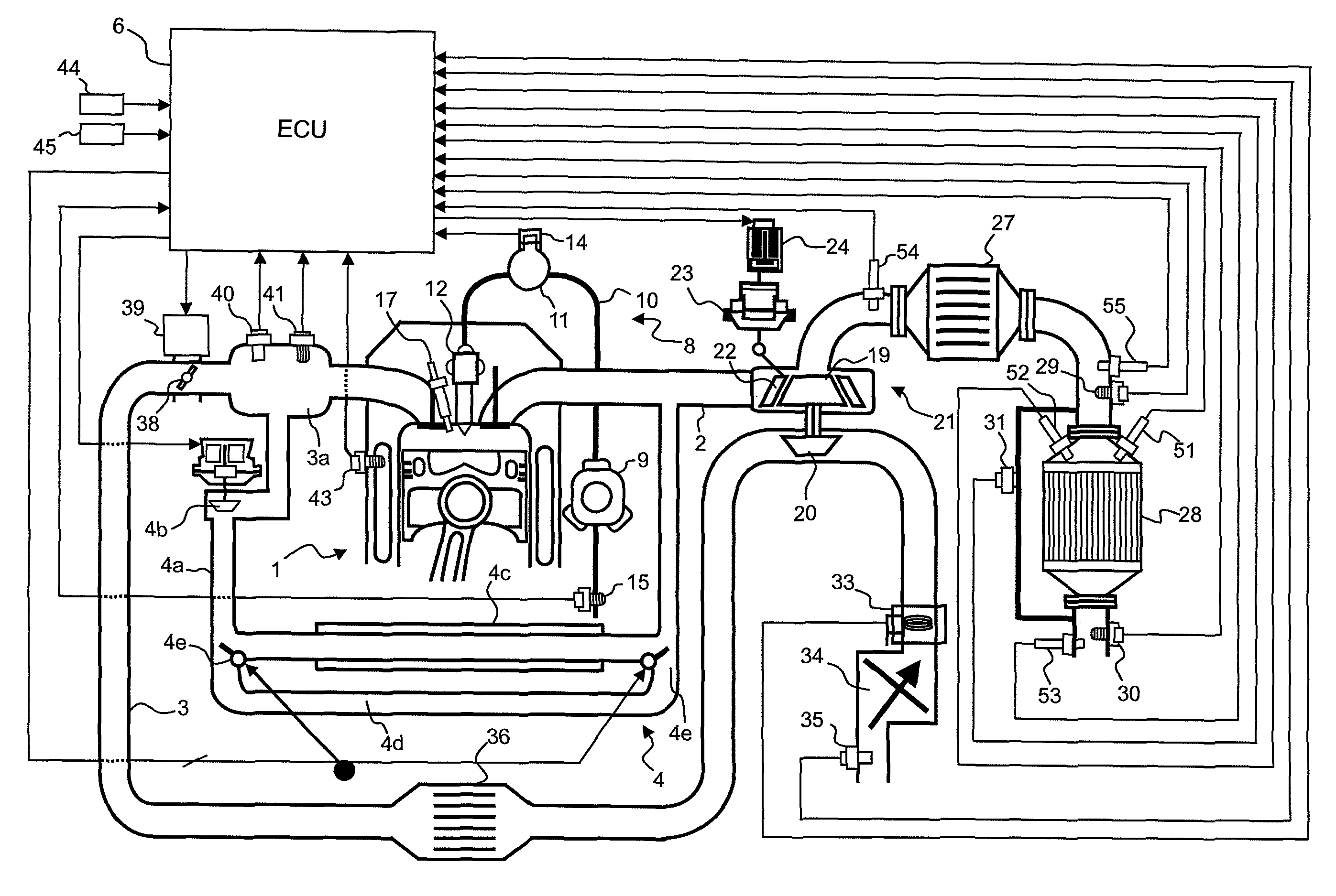
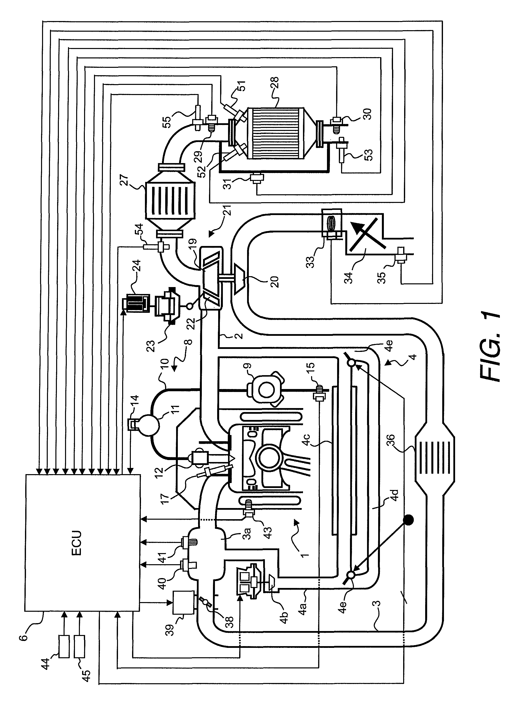
[0024]Referring initially to FIG. 1, an internal combustion engine 1 (e.g., a diesel engine) is illustrated with an exhaust gas cleaning apparatus in accordance with a first embodiment. The diesel engine 1 has an exhaust passage 2 to expel the exhaust gas from the combustion chamber of the diesel engine 1 and an intake passage 3 for introducing intake air into the combustion chamber of the diesel engine 1. The exhaust passage 2 equipped with an exhaust gas recirculation apparatus (EGR system) 4 for recirculating a portion of exhaust gas to an air induction system of the intake passage 3.

[0025]The e...


PUM


Abstract

An exhaust gas cleaning apparatus is provided with an exhaust gas particulate filter, an oxidation catalytic converter and a regeneration control component. The exhaust gas particulate filter is arranged in an exhaust passage of an internal combustion engine for capturing particulate matter in exhaust gas from the internal combustion engine. The oxidation catalytic converter is arranged upstream of the exhaust gas particulate filter in the exhaust passage. The regeneration control component is configured to control an exhaust gas recirculation rate and a temperature of recirculated exhaust gas being recirculated to an air induction system of the internal combustion engine for controlling a temperature of the exhaust gas particulate filter and a concentration of nitrogen dioxide in the exhaust gas particulate filter such that nitrogen dioxide generated by the oxidation catalytic converter is used to burn the particulate matter captured in the exhaust gas particulate filter.

Description

CROSS-REFERENCE TO RELATED APPLICATIONS[0001]This application claims priority to Japanese Patent Application No. 2007-122106, filed on May 7, 2007. The entire disclosure of Japanese Patent Application No. 2007-122106 is hereby incorporated herein by reference.BACKGROUND OF THE INVENTION[0002]1. Field of the Invention[0003]The present invention generally relates to an exhaust gas cleaning apparatus for an internal combustion engine. More specifically, the present invention relates to an exhaust gas cleaning apparatus that removes exhaust gas particulate matter captured in an exhaust gas particulate filter arranged in a downstream position by oxidizing the particulate matter using nitrogen dioxide (NO2) generated by an oxidation catalytic converter arranged in an upstream position.[0004]2. Background Information[0005]There are various known technologies for cleaning exhaust gas discharged from an engine. For example, Japanese Laid-Open Patent Publication No. 2005-315190 discloses a kn...

Claims


Application Information

Patent Timeline
Patent Type & Authority Patents(United States)
IPC IPC(8): F01N3/00
CPCF01N3/0231F01N9/002F01N11/007F02M25/0718F01N2560/025F02B29/0406F02M25/0707F02M25/0728F02M25/0738Y02T10/121Y02T10/47F02M26/05F02M26/15F02M26/25F02M26/33Y02T10/40
Inventor HOSAKA, YUUICHI
Owner NISSAN MOTOR CO LTD
Why Eureka
Try Eureka