
Yarn tensioning mechanism

a tensioning mechanism and yarn technology, applied in the field of yarn tensioning mechanism, can solve the problems of varying yarn elasticity, inability to precisely control contraction, waste of substantial amounts of yarn, etc., and achieve the effect of positive gripping and feeding yarns and no slippage of yarns

Inactive Publication Date: 2012-03-06
TUFTCO
View PDF7 Cites 20 Cited by
  • Summary
  • Abstract
  • Description
  • Claims
  • Application Information

AI Technical Summary

Benefits of technology

"The invention provides an improved system for controlling the feeding of yarns in tufting machines. The system uses teethed wheels to grip and feed yarns, and a tensioning and clamping device to keep the yarns under tension while they are being fed. This prevents slippage of yarns that are not selected for tufting. The technical effect of this system is to improve the accuracy and efficiency of tufting machines, resulting in better quality products."

Problems solved by technology

Due to the characteristics of yarns and the imprecise nature of pneumatically supplied yarn, the lengths of yarns tufted are generally not uniform and the resulting fabrics not only require tip shearing but also result in the waste of substantial amounts of yarn.
Different yarns have differing elasticities so the contraction is not precisely controllable.
Additionally, even in the case of yarns fed by conventional means, varying yarn elasticity contributes to less uniform output.

Method used


Image

  • Yarn tensioning mechanism
  • Yarn tensioning mechanism
  • Yarn tensioning mechanism

Examples


Embodiment Construction

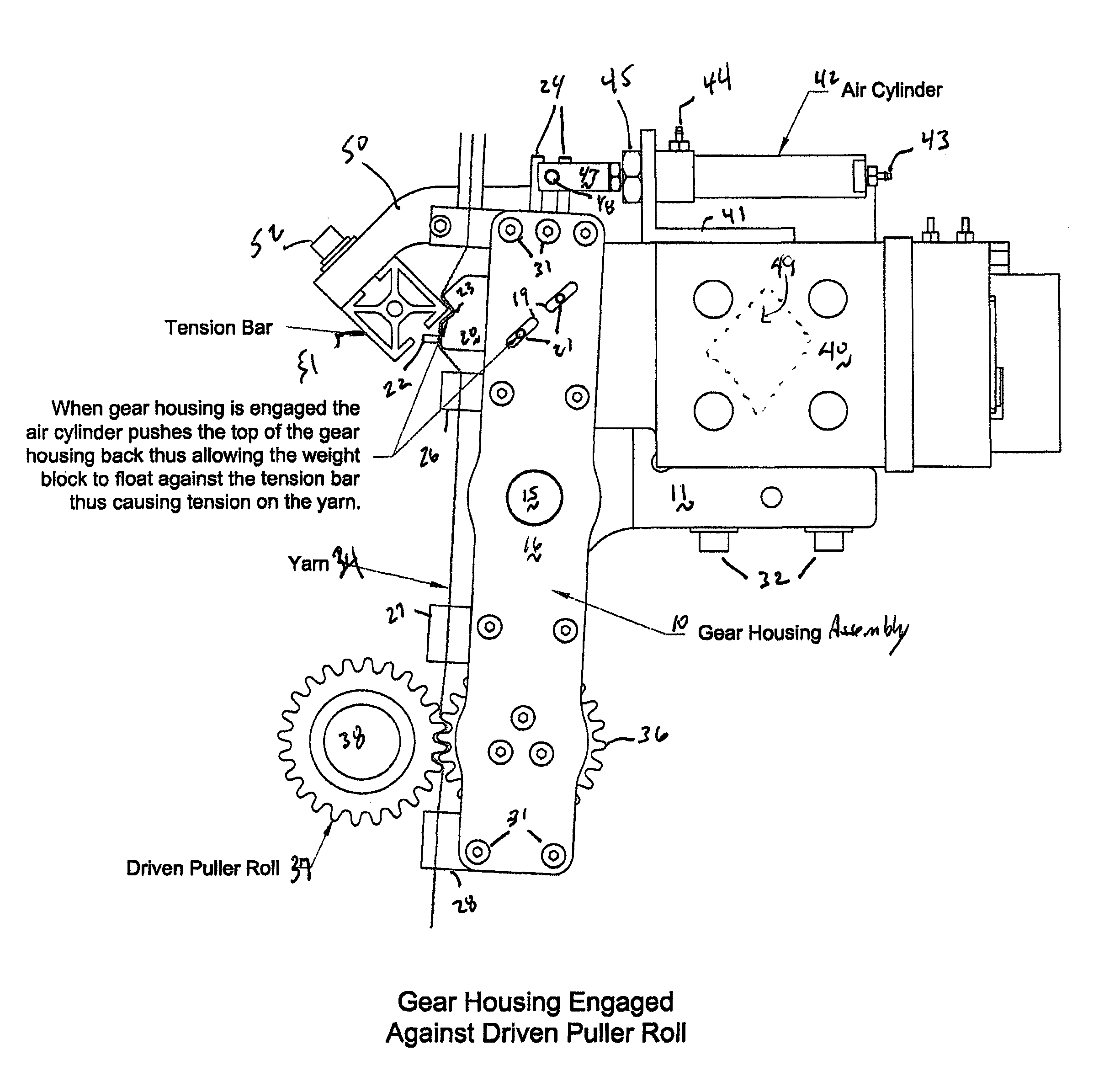
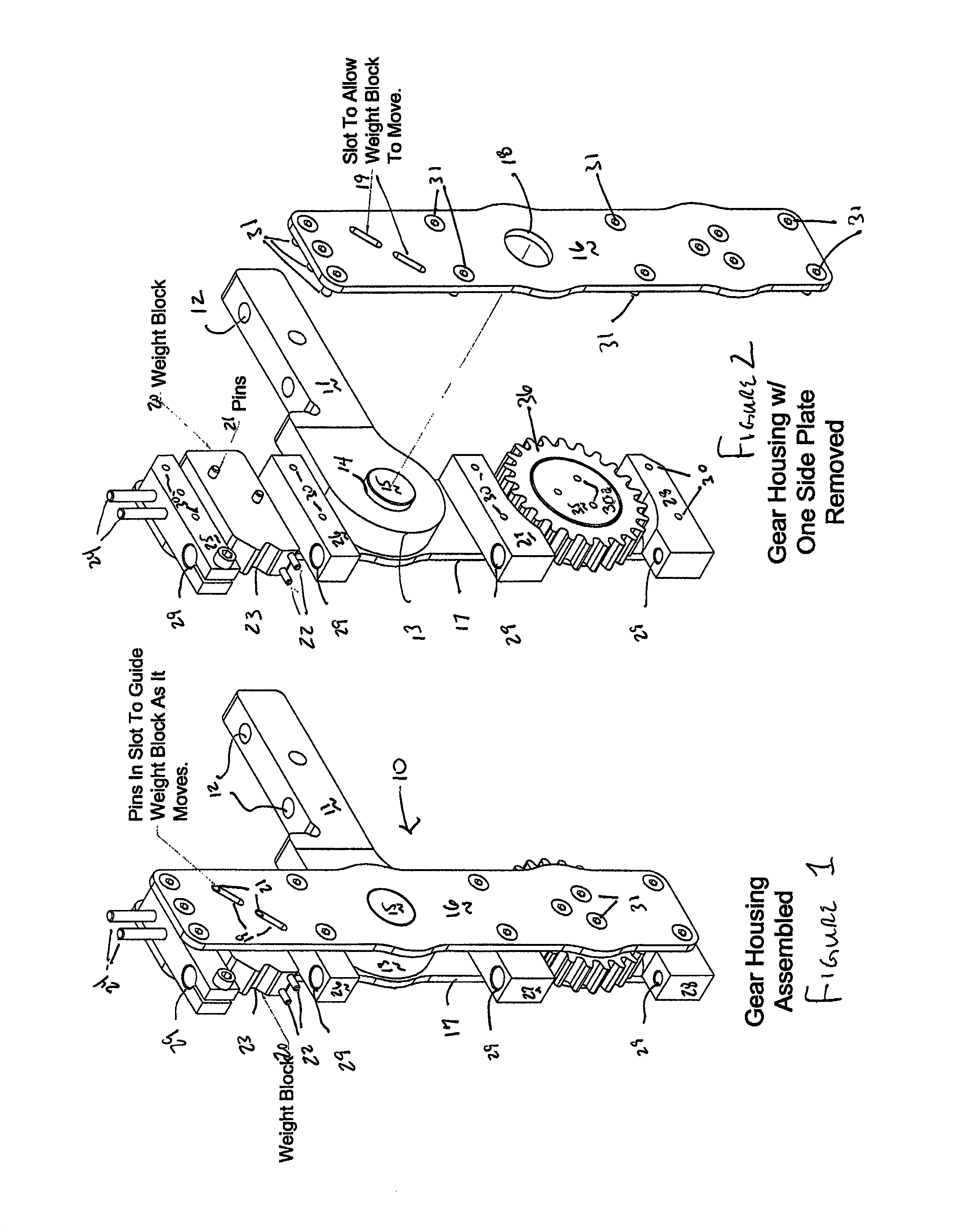
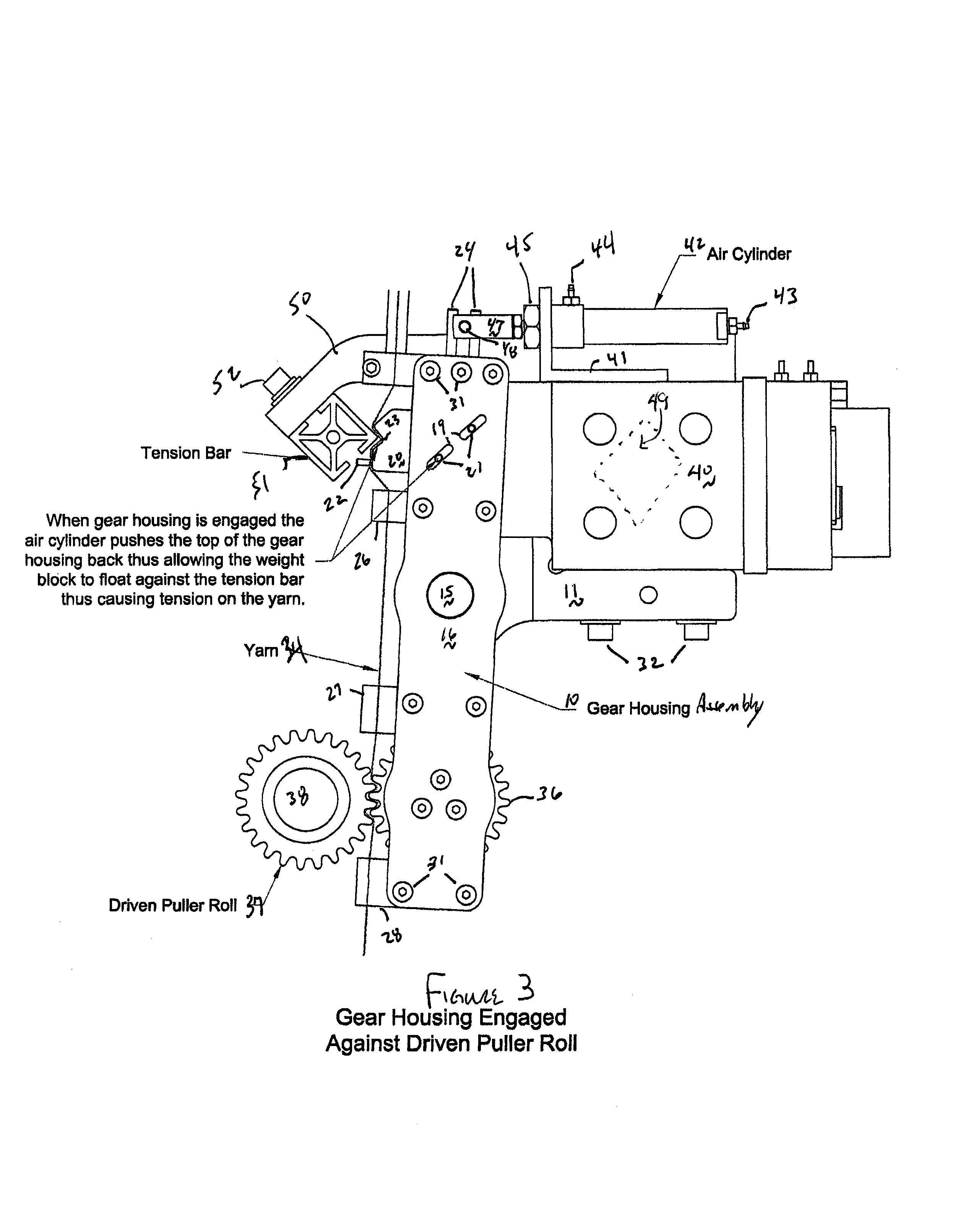
[0015]In FIGS. 1 and 2 a gear housing assembly 10 designed to provide precise yarn feed and yarn tensioning control is illustrated. The principal elements of gear housing assembly 10 are coupling pins 24, weight block 20, mounting bar 11, and teethed yarn roll 36. These elements are carried in a structure comprising first side plate 16 and second side plate 17 with fasteners 31 that are received in fastener openings 30 located in top fastening block 25, second fastening block 26, third fastening block 27, and bottom fastening block 28. In addition, some fasteners 31 are received within openings 30a in bearing support 35.

[0016]Turning then to the principal features of the gear housing assembly 10, the coupling pins 24 extend upwards and operate in conjunction with a clevis 47 and clevis pin 48 illustrated in FIGS. 3 and 4 to apply pressure at the top of the gear housing assembly on coupling pins 24. Mounting bar 11 has vertical openings 12 which, as shown on FIGS. 3 and 4, receive fa...


PUM


Abstract

A yarn tensioning apparatus is supplied with a yarn clamping position and a positive yarn engaging position to precisely meter yarns to tufting machine needles and especially to more uniformly advance pneumatically supplied yarns to hollow needles.

Description

[0001]The present application claims priority to the Jul. 21, 2008 filing date of U.S. provisional patent application Ser. No. 61 / 082,311.FIELD OF THE INVENTION[0002]The present invention is addressed to more precisely feeding yarns for sewing fabrics, and is especially adapted to the feeding of yarns that are pneumatically supplied for tufting, as via a hollow needle.BACKGROUND OF THE INVENTION[0003]In most hollow needle tufting machines, as typified by Kile, U.S. Pat. No. 4,549,496; Davis, et al., U.S. Pat. No. 5,588,383 and Ingram, U.S. Pat. No. 7,318,383, yarns are selectively fed to hollow needles by pneumatic pressure. Where the yarn being fed to a particular needle is changed, Kile and Davis found it necessary to retract the previously fed yarn from the hollow needle and to pneumatically urge the newly selected yarn to extend through the hollow needle to the appropriate length for tufting. Due to the characteristics of yarns and the imprecise nature of pneumatically supplied ...

Claims


Application Information

Patent Timeline
Patent Type & Authority Patents(United States)
IPC IPC(8): D05C15/18D05B47/00
CPCD05B47/00D05C15/18
Inventor INGRAM, GARY L.
Owner TUFTCO
Learn More