Device and method for coupling a conduit

a technology of coupling conduits and devices, which is applied in the direction of fluid pressure sealing joints, branching pipes, pipe elements, etc., can solve the problems of reducing installation costs and reducing manufacturing costs, and achieve the effect of facilitating installation and modification of cabling infrastructur

Active Publication Date: 2012-03-06
IPEX TECH
View PDF35 Cites 27 Cited by
  • Summary
  • Abstract
  • Description
  • Claims
  • Application Information

AI Technical Summary

Benefits of technology

[0010]Accordingly, it is an object of this invention to at least partially overcome some of the disadvantages of the prior art. Also, in at least some aspects, this invention provides an improved device and method for facilitating installation and modification of cabling infrastructure in buildings.
[0013]Accordingly, one of the advantages of at least some of the aspects of the invention comprises a coupling device having two sides which can be snap fitted together to facilitate installation and thereby decrease installation costs. Furthermore, in a preferred embodiment, the two sides may be identical which may decrease the manufacturing costs in that a single mold can be used to make both sides of the coupling device. This also may decrease the installation costs because users need only purchase and store one side of the coupling device which can then be used to create the coupling device. Furthermore, if one side of the coupling device is damaged, users need not purchase two new sides, but rather simply use one of the other identical sides. Furthermore, if the sides are identical, they may be more easily stacked for storage and transportation.
[0014]A further advantage of at least some embodiments of the present invention is that the coupling device, when installed, engages the conduits to hold it in place, such as by creating an interference fit with the conduit including a friction fit. In this way, additional elements, such as sleeves, screws, tapes or adhesives, or, more complicated coupling methods, are not required. Rather, the openings of the coupling device are sized to create an interference fit with the conduit. In cases where the conduit is a corrugated conduit, the openings are sized to engage the corrugated conduit by fitting into the outer diameter of one of the corrugated corrugations. In a still further preferred embodiment, the coupling device, when manufactured, may have conical openings with pre-scored cut lines that can be cut at different diameters. In this way, the conical ends can be cut to fit the outer diameter of a corrugation of the corrugated conduits having different diameters to engage the conduit such as through an interference fit or friction fit. This increases the versatility of the coupling device. This also facilitates use of the coupling device to retrofit existing cabling infrastructure which may have conduits of different sizes.
[0015]A further advantage of at least some embodiments of the present invention is that it is light weight. In particular, the coupling device can be manufactured from rigid plastic material, such as PVDF or PVC and other materials permitted for use in plenums and / or as raceways or risers. These materials are relatively light, but nevertheless meets applicable fire, building and electrical codes standards. Furthermore, because of the durability of this material, the thickness of the sides of the coupling device can be relatively thin, such as less than 0.5 inches, and more preferably, less than 0.25 inches and still more preferably between 0.05 to 0.2 inches, on average. Furthermore, the material having this thickness can be relatively resilient, which facilitates the snap fitting of the one side onto the other side.

Problems solved by technology

Furthermore, in a preferred embodiment, the two sides may be identical which may decrease the manufacturing costs in that a single mold can be used to make both sides of the coupling device.
This also may decrease the installation costs because users need only purchase and store one side of the coupling device which can then be used to create the coupling device.
Furthermore, if one side of the coupling device is damaged, users need not purchase two new sides, but rather simply use one of the other identical sides.

Method used


Image

  • Device and method for coupling a conduit
  • Device and method for coupling a conduit
  • Device and method for coupling a conduit

Examples


Embodiment Construction

[0028]Preferred embodiments of the invention and its advantages can be understood by referring to the present drawings. In the present drawings, like numerals are used for like and corresponding parts of the accompanying drawings.

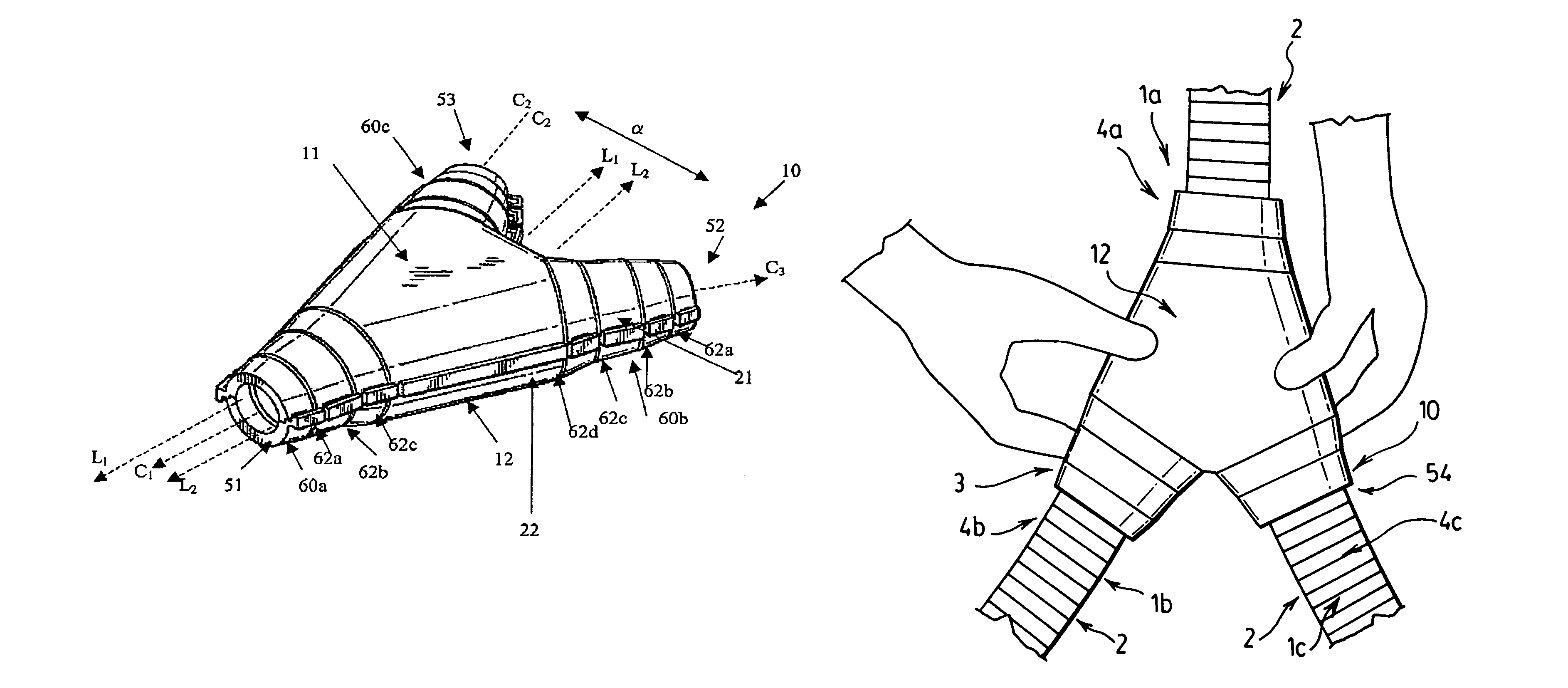
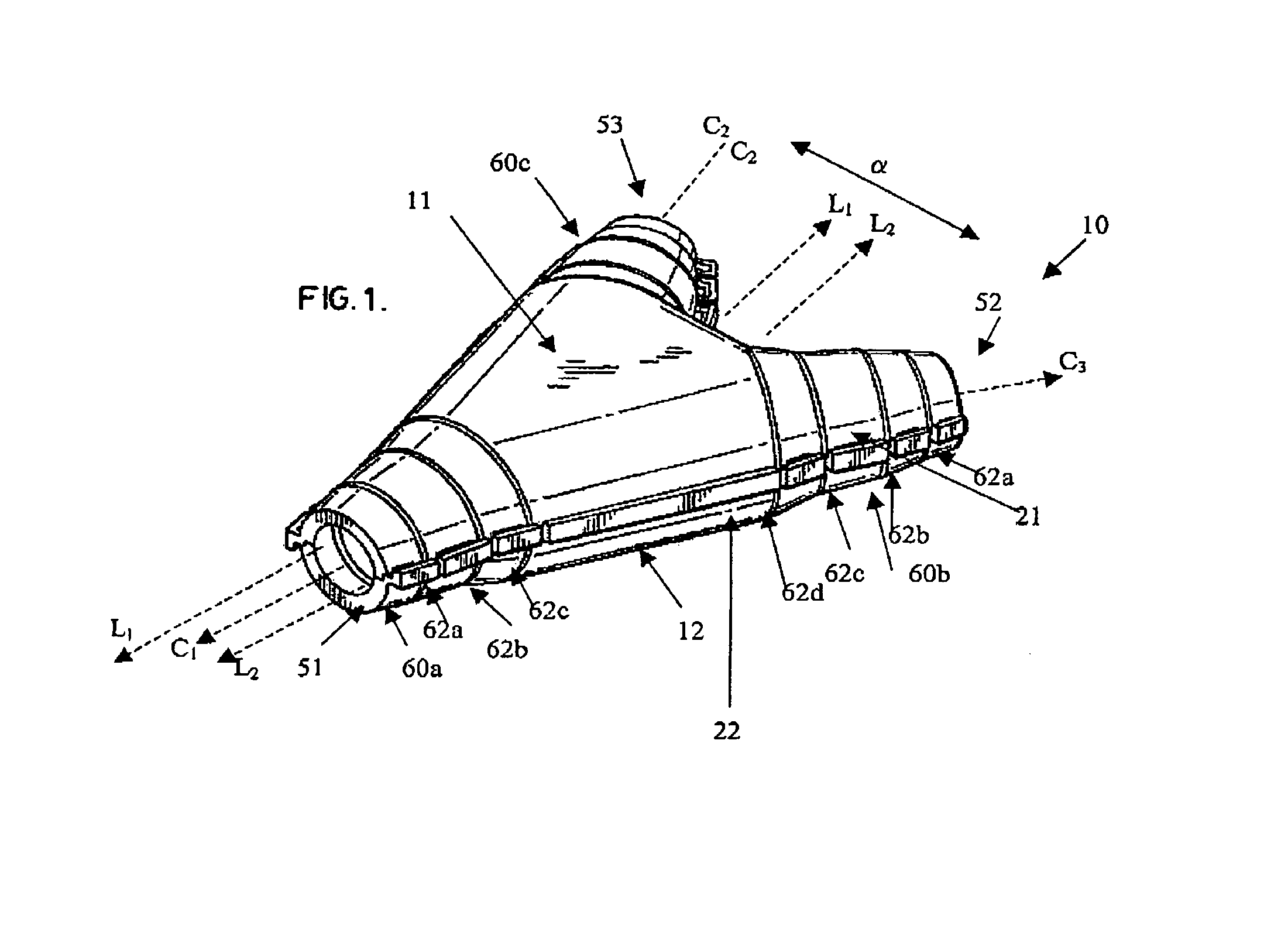
[0029]As shown in FIG. 1, one embodiment of the present invention relates to a coupling device, shown generally by reference numeral 10, which can be used to couple together conduits shown generally as reference numeral 1 in FIGS. 8 to 11. While the coupling device 10 in FIG. 1 illustrates the preferred embodiment where the ends 4 of three conduits 1a, 1b, 1c are coupled together, it is understood that the coupling device 10 may have other embodiments for coupling together two, three, four or more conduits 1.

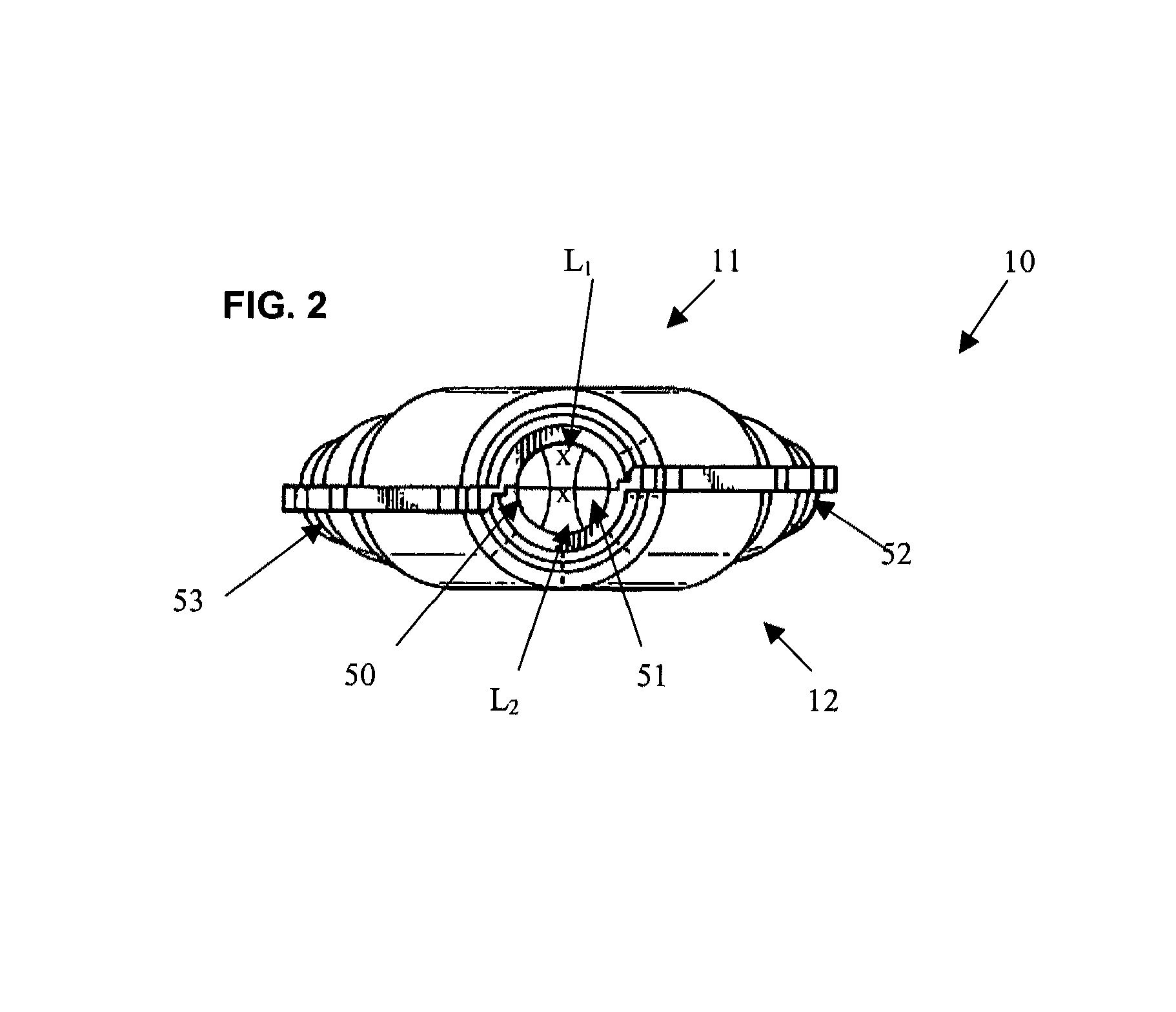
[0030]As illustrated in FIG. 1, as well as FIGS. 2, 3 and 4, the coupling device 10 according to one preferred embodiment, has a first side 11 with a snap fitting mechanism 21. The coupling device 10 also comprises a second side 12 having a second snap ...


PUM


Abstract

A coupling device formed of two identical sides is disclosed. Each of the two sides have a snap fitting mechanism which engage each other to releasably secure the sides together thereby forming the coupling device. The coupling device as formed has a main body communicating with at least two openings. Each opening is sized to engage an end of a corresponding conduit. Generally, the conduits are corrugated such that the openings engage one corrugation to form the friction fit. The openings may be conically shaped with pre-scored cut lines that can be cut at different diameters to engage conduits of different diameters. The openings of the coupling device have pre-score cut lines that may be cut in order to create the friction fit with corrugated conduits having different diameters.

Description

FIELD OF THE INVENTION[0001]This invention relates to a device and method for coupling conduits. More particularly, the invention relates to a coupling device and method for using same to couple together two or more conduits, such as used in risers and plenums.BACKGROUND OF THE INVENTION[0002]With the evolution of today's integrated network environments in both homes and businesses, the design of a building's cabling infrastructure has become more demanding than ever before. Not only has system performance become critical, but consumers now demand mobility and flexibility, while maintaining low installation and maintenance costs.[0003]As technology continues to evolve and traditional optical fibre and communications cabling methods become obsolete, designing or retrofitting buildings with optical fibre and communication cable raceways has become more common. This combines compliance with fire, building and electrical code requirements with the demands of users to be both flexible an...

Claims


Application Information

Patent Timeline
Patent Type & Authority Patents(United States)
IPC IPC(8): F16L39/00
CPCF16L21/06F16L41/023
Inventor POUPORE, TIMOTHY J.LECLERC BOUTIN, ERICYOUSSEF, YOUNES
Owner IPEX TECH
Why Eureka
Try Eureka