Supercharge Your Innovation With Domain-Expert AI Agents!

Television broadcast signal receiving system, television broadcast signal receiving apparatus, and antenna apparatus

a technology for receiving systems and television broadcasts, applied in the field of television broadcast signal receiving systems, can solve the problems of more needless time and long setting time, and achieve the effect of reducing the number of needless tim

Inactive Publication Date: 2012-03-06
FUNAI ELECTRIC CO LTD
View PDF15 Cites 0 Cited by
  • Summary
  • Abstract
  • Description
  • Claims
  • Application Information

AI Technical Summary

Benefits of technology

This solution significantly reduces the time required for channel auto scanning by allowing automatic selection and setting of the best frequency bands and receiving directions, enhancing user convenience and efficiency in receiving broadcast signals across different frequency bands.

Problems solved by technology

However, when auto scanning of channels is executed by using the smart antenna and the auto scanning function which are disclosed in the above mentioned prior art, there is a problem that it takes a long time to carry out the setting because the scanning is carried out in all 16 directions for each channel whether the TV broadcast signal is in the VHF band or the UHF band.
Therefore, more needless time may be spent even when the above mentioned prior art is used to set a channel in the VHF band.
Therefore, when carrying out the channel auto scanning process in the television broadcast signal receiving apparatus, the best suitable frequency range (range of channels which can be received) is not necessarily always set for each antenna.

Method used


Image

  • Television broadcast signal receiving system, television broadcast signal receiving apparatus, and antenna apparatus
  • Television broadcast signal receiving system, television broadcast signal receiving apparatus, and antenna apparatus
  • Television broadcast signal receiving system, television broadcast signal receiving apparatus, and antenna apparatus

Examples


Embodiment Construction

[0028]Hereinafter, a preferred embodiment of the present invention is described with reference to the drawings. However, the drawings are in no way to limit the scope of the invention.

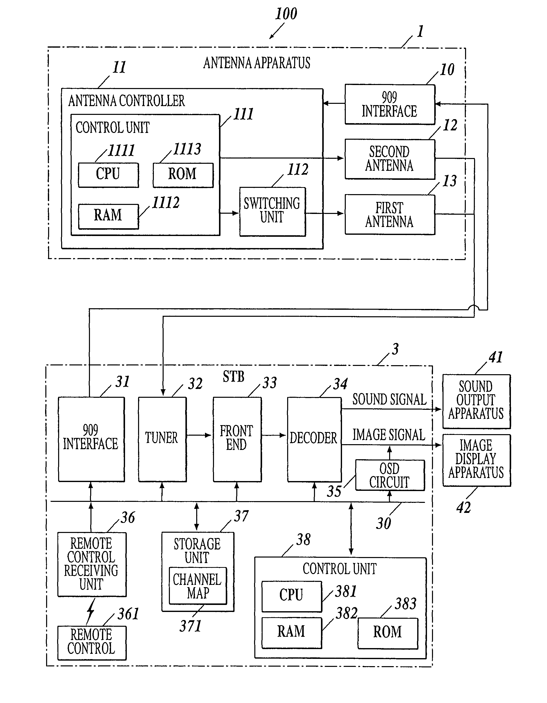
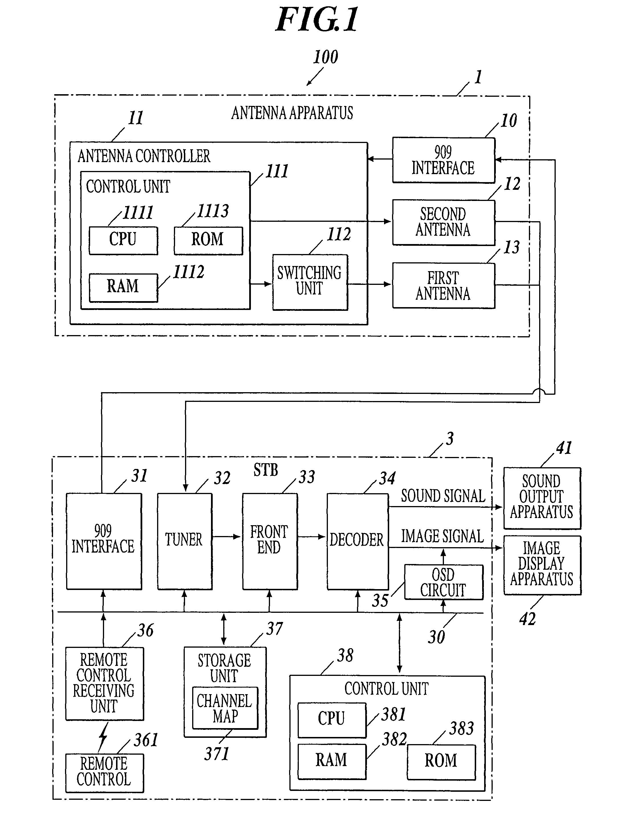
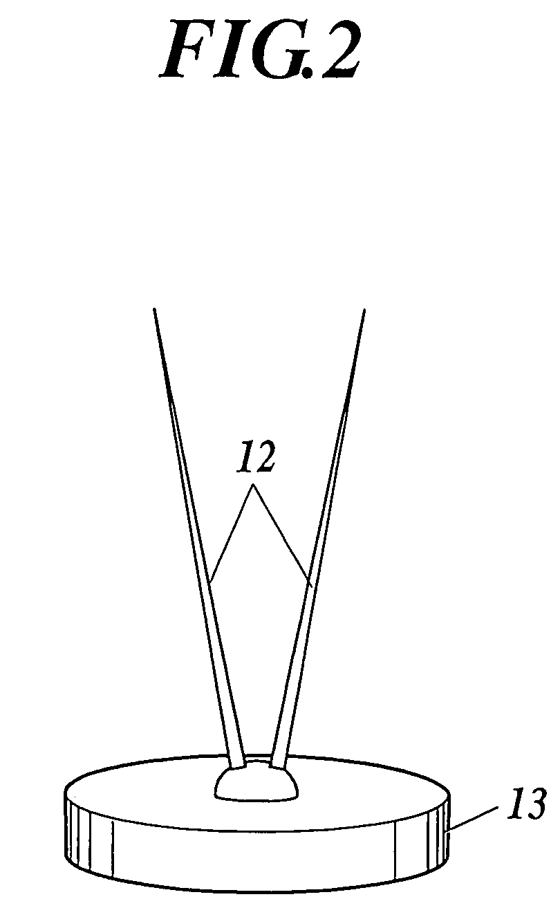
[0029]FIG. 1 is a block diagram showing a functional structure of a television broadcast signal receiving system and FIG. 2 is a perspective view showing an outer appearance of an antenna apparatus 1.

[0030]The television broadcast signal receiving system 100 according to the embodiment comprises an antenna apparatus 1 which can receive broadcast signals from a plurality of directions and a Set Top Box (hereinafter, abbreviated as STB) 3 as a television broadcast signal receiving apparatus to which the antenna apparatus 1 is connected.

[0031]The antenna apparatus 1, for example, is controlled by the STB3 based on a predetermined standard (for example, the EIA / CEA-909 or the like), and is constructed so that the information relating to the antennal apparatus 1 (identification information and the like) can...


PUM


Abstract

A television broadcast signal receiving system including an antenna apparatus including a first antenna which can receive a broadcast signal in a first frequency band and a second antenna which can receive a broadcast signal in a second frequency band and a television broadcast signal receiving apparatus including a selection unit for selecting the first antenna or the second antenna according to a frequency of a broadcast signal which is to be received, a detecting unit for detecting a receiving level of a received signal which is received by the first antenna or the second antenna, a channel setting unit for setting a channel of the broadcast signal in which the receiving level detected by the detecting unit is not less than a predetermined value as a receivable channel, and a control unit for controlling each operation of the selection unit, the detecting unit, and the channel setting unit.

Description

BACKGROUND OF THE INVENTION[0001]1. Field of the Invention[0002]The present invention relates to a television broadcast signal receiving system which can receive television broadcast signals in the UHF band and the VHF band, and more particularly, to a television broadcast signal receiving apparatus having a channel auto scanning (channel auto setting) function using a multiple directional antenna and an antenna apparatus suitable to the television broadcast signal receiving apparatus.[0003]2. Description of the Related Art[0004]In North America where the ATSC digital television broadcast (hereinafter, abbreviated as TV broadcast) is carried out, TV broadcast signals are transmitted from-various directions because large cities are scattered across the plain area and a number of broadcasting station exist. In such environment, viewers who receive the TV broadcast signals need to adjust the receiving direction of the antenna in the direction of a broadcasting station in which the prog...

Claims


Application Information

Patent Timeline
Patent Type & Authority Patents(United States)
IPC IPC(8): H04N5/44H04B1/18H04N7/173
CPCH01Q1/24H01Q3/24H04B1/0067
Inventor ONOMATSU, TAKEHIRO
Owner FUNAI ELECTRIC CO LTD
Features
  • R&D
  • Intellectual Property
  • Life Sciences
  • Materials
  • Tech Scout
  • Unparalleled Data Quality
  • Higher Quality Content
  • 60% Fewer Hallucinations
Learn More