Apparatus for generating software logic rules by flowchart design

a flowchart design and software logic technology, applied in the field of apparatus for generating software logic rules by flowchart design, can solve the problems that the translation of flowcharts into automated processes currently requires a great deal of custom programming, and achieve the effect of facilitating the translation of flowcharts

Active Publication Date: 2012-03-06
TAYLOR BLAISE DIEUDONNE
View PDF47 Cites 39 Cited by
  • Summary
  • Abstract
  • Description
  • Claims
  • Application Information

AI Technical Summary

Benefits of technology

[0008]According to the first embodiment of the present invention, the variables configuration form, the functions configuration form and the parameters configuration form allow the software developer to store metadata about the functions and variables which facilitates the translation of flow diagrams into rules in XAML which will be loaded and executed by the Windows Workflow Foundation (WF) Rules Engine.
[0009]According to the second embodiment

Problems solved by technology

Turning a flow chart into an automated process cur

Method used


Image

  • Apparatus for generating software logic rules by flowchart design
  • Apparatus for generating software logic rules by flowchart design
  • Apparatus for generating software logic rules by flowchart design

Examples


first embodiment

Creation of Rules for Windows WF Rules Engine in XAML

1 Abstract

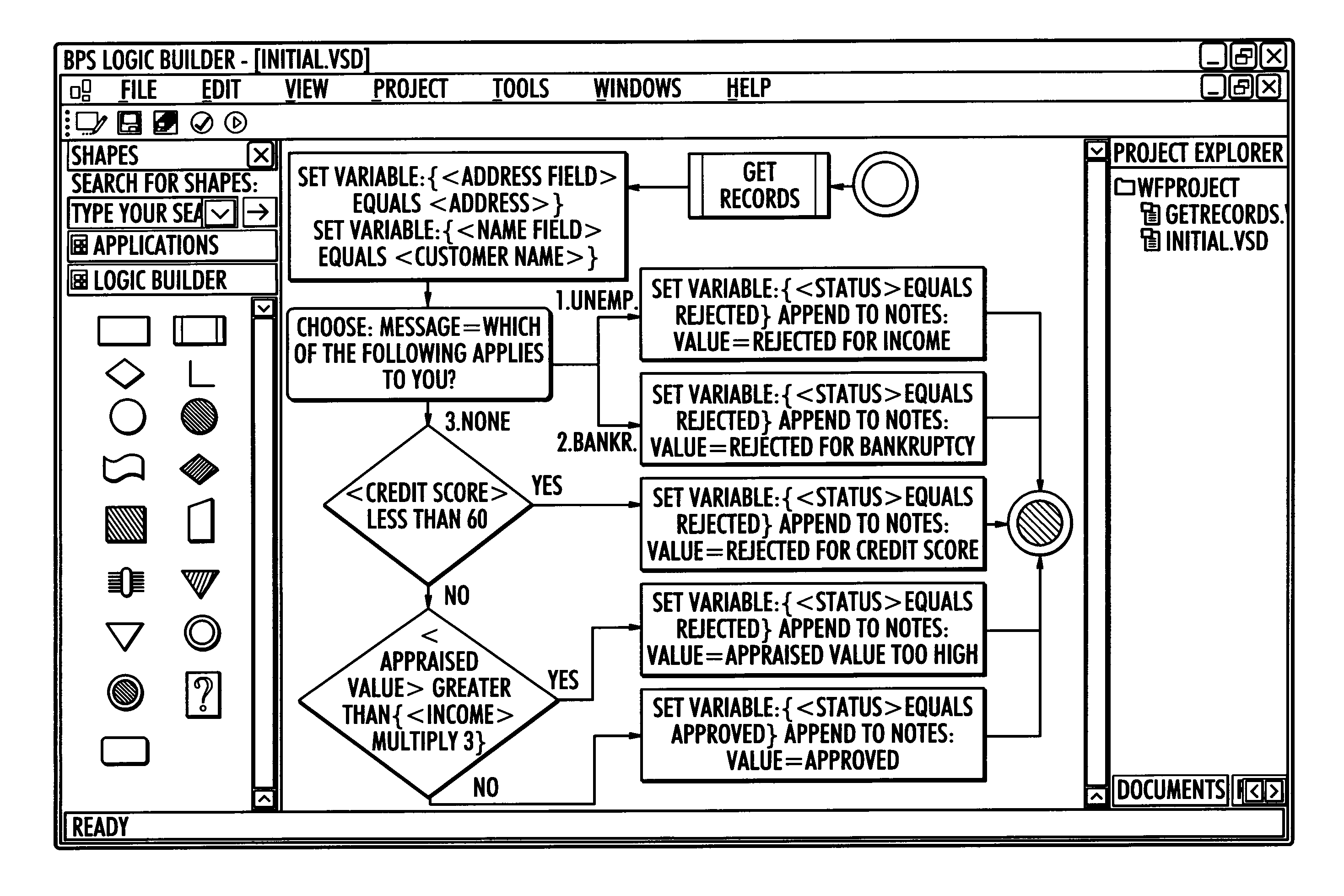
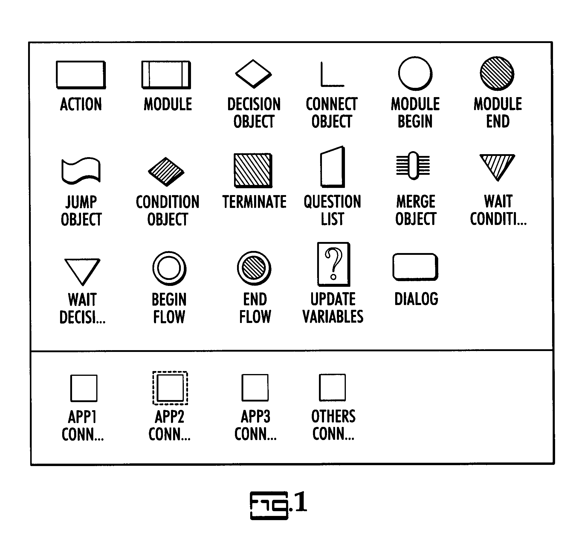
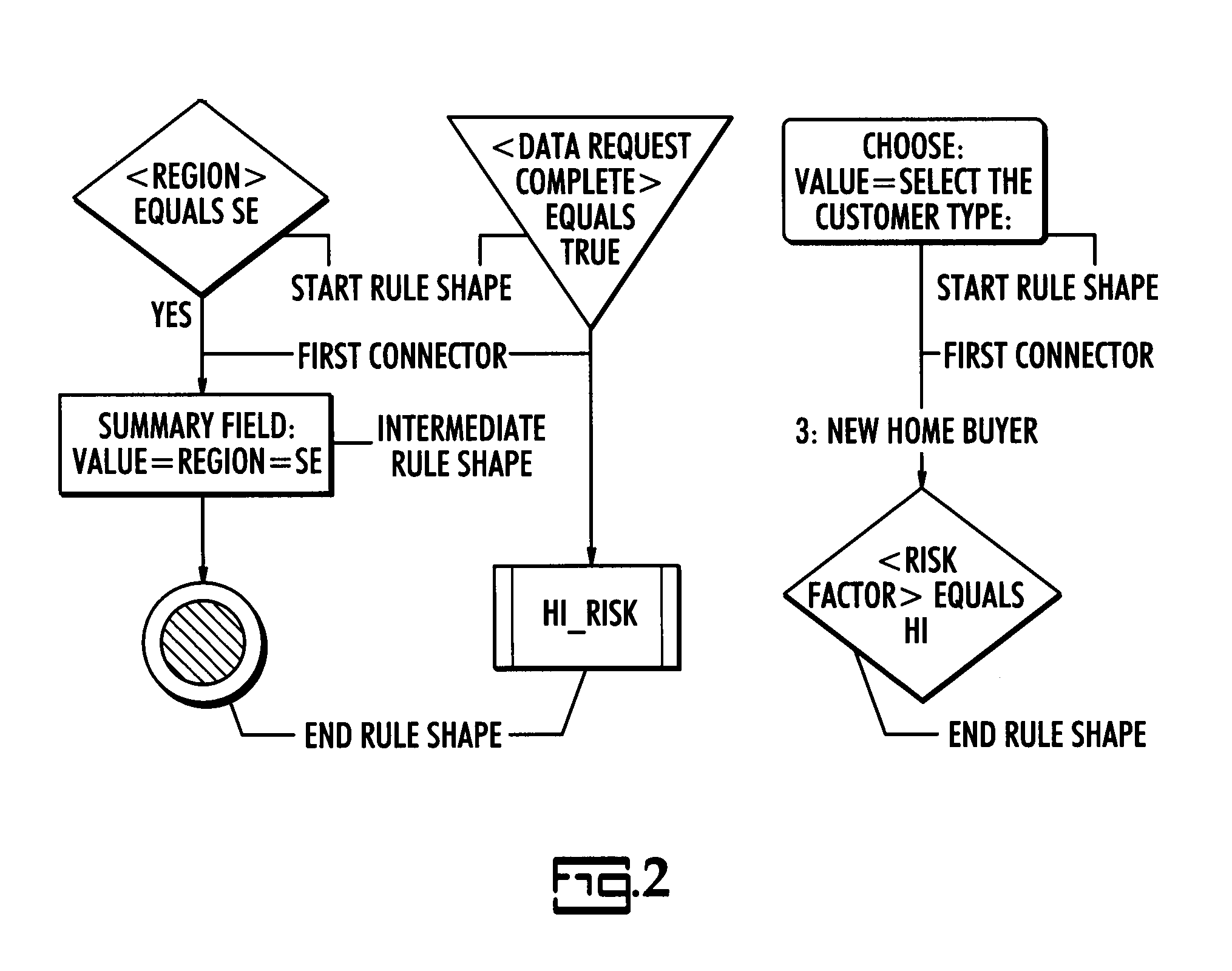
[0061]In summary the present invention is defined in three parts:[0062]1) A Developer Interface that performs a mapping of functions, variables and project properties between the present invention and the business application.[0063]2) An Editing Interface that allows the business user to define the rules in the form of flow diagrams and tables using the functions and variables defined in the Developer Interface.[0064]3) The Rules Generator that then parses the flow diagrams and tables defined by the business user and using the functions and variables defined in the Developer Interface, creates rules for the Windows WF Rules Engine in XAML. The rules can then be deployed to a business application that may reside on the same local area network.

2 Developer Interface

2.1 Functions

Functions define the mapping between methods in the Activity Class of the business application and the functions used in present invention to define...


PUM


Abstract

A apparatus implemented using a programmable computer that automatically generates the rules required by a software rules engine as a process flow diagram is designed. The apparatus includes a developer interface; an editing interface, and a rules generator. A developer interface enables the user to define functions and variables together with their properties from the business application. An editing interface allows the user to define the logical rules the business would follow in performing the business application by constructing a process flow diagram and associated tables using the functions and variables defined in the developer interface. The rules generator then automatically parses the flow diagrams and tables defined by the business user and, using the functions and variables defined in the developer interface, generates rules for a rules engine. The rules can then be deployed to a controller that implements the process automatically based on the input rules.

Description

PRIORITY CLAIM[0001]The priority benefit of U.S. provisional patent application Ser. No. 60 / 979,505, filed Oct. 12, 2007, is claimed. Provisional patent application 60 / 979,505 is hereby incorporated in its entirety by reference.SUMMARY OF THE INVENTION[0002]According to its major aspects and briefly recited, the present invention is an apparatus implemented using a programmable computer that is used to develop a flow chart of a process and to generate the rules needed by a rules engine to implement that process. In the development of this flow chart, the user makes choices from dialogs that automatically enable the apparatus to produce software logical rules in a computer language. These software rules, which are the logically related steps needed to automate the process, may then be read directly by a rules engine to implement process defined by the flow chart.[0003]An important feature of the present invention is the use of standard flow diagram shapes and connectors not only to d...

Claims


Application Information

Patent Timeline
IPC IPC(8): G06F17/00G06F9/44G06N7/00G06N7/08
CPCG06F8/34
Inventor TAYLOR, BONAMY
Owner TAYLOR BLAISE DIEUDONNE
Why Eureka
Try Eureka