Rankline-Brayton engine powered solar thermal aircraft

a solar thermal and engine technology, applied in the direction of machines/engines, energy-saving board measures, and efficient propulsion technologies, can solve the problems of reducing the efficiency of solar power collection, and regenerative fuel cell systems imposing a substantial weight burden on all aircraft, etc., to achieve high specific power engine design, high thermal efficiency, and large pressure drop

Inactive Publication Date: 2012-03-13
LAWRENCE LIVERMORE NAT SECURITY LLC
View PDF8 Cites 16 Cited by
  • Summary
  • Abstract
  • Description
  • Claims
  • Application Information

AI Technical Summary

Benefits of technology

[0039]And the Rankine-Brayton hybrid thermodynamic cycle-based power plant of the present invention is essentially a hybrid of the bottom half of a Rankine process in the lower temperature portion of the cycle together with the top half of a Brayton-like process in the higher temperature portion of the cycle, linked by a recuperating heat interchanger. More specifically, the working fluid is: first, condensed to liquid at sub-critical pressure and temperature; second, raised in pressure by a fluid pump to supercritical pressure, but sub-critical temperature; third, heated to supercritical pressure and temperature; fourth, lowered in pressure by an expander to supercritical temperature but sub-critical pressure; and finally, cooled to sub-critical temperature and pressure to start the cycle again. A substantial fraction of the heating of the high-pressure working fluid is provided via heat interchange from the cooling of the low-pressure working fluid after expansion. Since the working fluid is at super-critical pressure after the pump, it can be heated without danger of generating a mixture of gas and liquid phases, and so it is not necessary to incorporate a gas-liquid phase separator, as is generally required in conventional steam power plants. In addition, the power extracting expansion of the working fluid, by virtue of the supercritical to sub-critical pressure transition, produces a large pressure drop with only a modest temperature drop compared to the case of an ideal gas expansion. This small temperature drop is a significant factor in enabling high thermal efficiency. And by virtue of the choice of working fluid, the large pressure drop from supercritical to sub-critical pressure can be attained with a quite modest volume expansion ratio, and this fact enables the use of a single stage of expansion in the engine and this in turn enables a very compact and high specific power engine design. Finally, in view of the wide span of power levels envisioned for a solar powered aircraft that preferably adjusts power levels sufficiently to maintain station in the face of widely varying winds, and in view of the difficulty of achieving high efficiency with turbo-machinery over a wide span of power levels, it is preferred to implement the engine as a positive displacement device, such as the reciprocating piston engine described here as the preferred embodiment.

Problems solved by technology

It is widely recognized, however, that onboard voltaic batteries or electrolyzer, gas storage, and regenerative fuel cell systems impose a substantial weight burden for all aircraft, and especially for high-altitude, long range aircraft.
Another problem associated with photovoltaic power generation arrangements for aircraft, especially high-altitude, long-range aircraft, is the need to orient / point the photovoltaic solar cells to face the sun.
Having wing-mounted arrays of solar panels can limit the efficiency of the collection of solar power, especially at dawn and dusk, as sunlight seldom strikes the solar panels “face on”.
Conventional aircraft, however, cannot maintain straight flight at a large bank angle for extended lengths of time.
Moreover, a related problem is the significant restriction on the latitude range over which aircraft may be flown, often seen with wing mounted solar energy collection means, i.e. photovoltaic solar cells, characteristic of the prior art.
During winter, at higher northern latitudes, the maximum angle of the sun above the horizon may be relatively small, and thus the effective collection area of the wing surface may be severely restricted.
While the Phillips reference alternatively suggests that solar cells may be placed on a tilting panel within a transparent fuselage structure, this arrangement would require the inclusion of a cooling system for the inner located cells, with the associated weight and aerodynamic drag penalties.
The cooling requirement discussed in Phillips for maintaining high efficiency of inside-mounted cells is a generic limitation common to all photo-voltaic solar cell powered aircraft.
This same limitation precludes the practical use of solar cells at the focus of a high concentration factor solar collector, since excessive heating of solar cells leads to substantially reduced efficiency.
Furthermore, the efficiency of photovoltaic electric energy collection, storage, and utilization in the prior art is relatively limited.
Photovoltaic arrays of high efficiency are very expensive and tend to lose efficiency at elevated temperatures, and thus are not practical to use at the focus of a high flux solar concentrator.
None of these representative references, however, disclose how the solar energy generation and storage system can be made sufficiently lightweight that it would be able to provide for the overnight propulsion of a solar-powered aircraft.
The '653 patent, however, does not disclose how highly reactive LiH may be safely contained for long periods of time.
In addition to the problems associated with photovoltaic power generation and solar energy collection / storage for solar aircraft described above, the operational requirements on the power plant of a solar thermal aircraft to enable it to remain aloft through the day / night cycle are extraordinarily demanding.
The power to mass ratio is therefore critical for solar thermal aircraft applications, since below a certain level, the aircraft cannot function as desired.
Such plants are typically limited in thermal efficiency to less than 20%.

Method used


Image

  • Rankline-Brayton engine powered solar thermal aircraft
  • Rankline-Brayton engine powered solar thermal aircraft
  • Rankline-Brayton engine powered solar thermal aircraft

Examples


Embodiment Construction

[0066]Reference numerals used in the following description are listed in Table 1.

[0067]

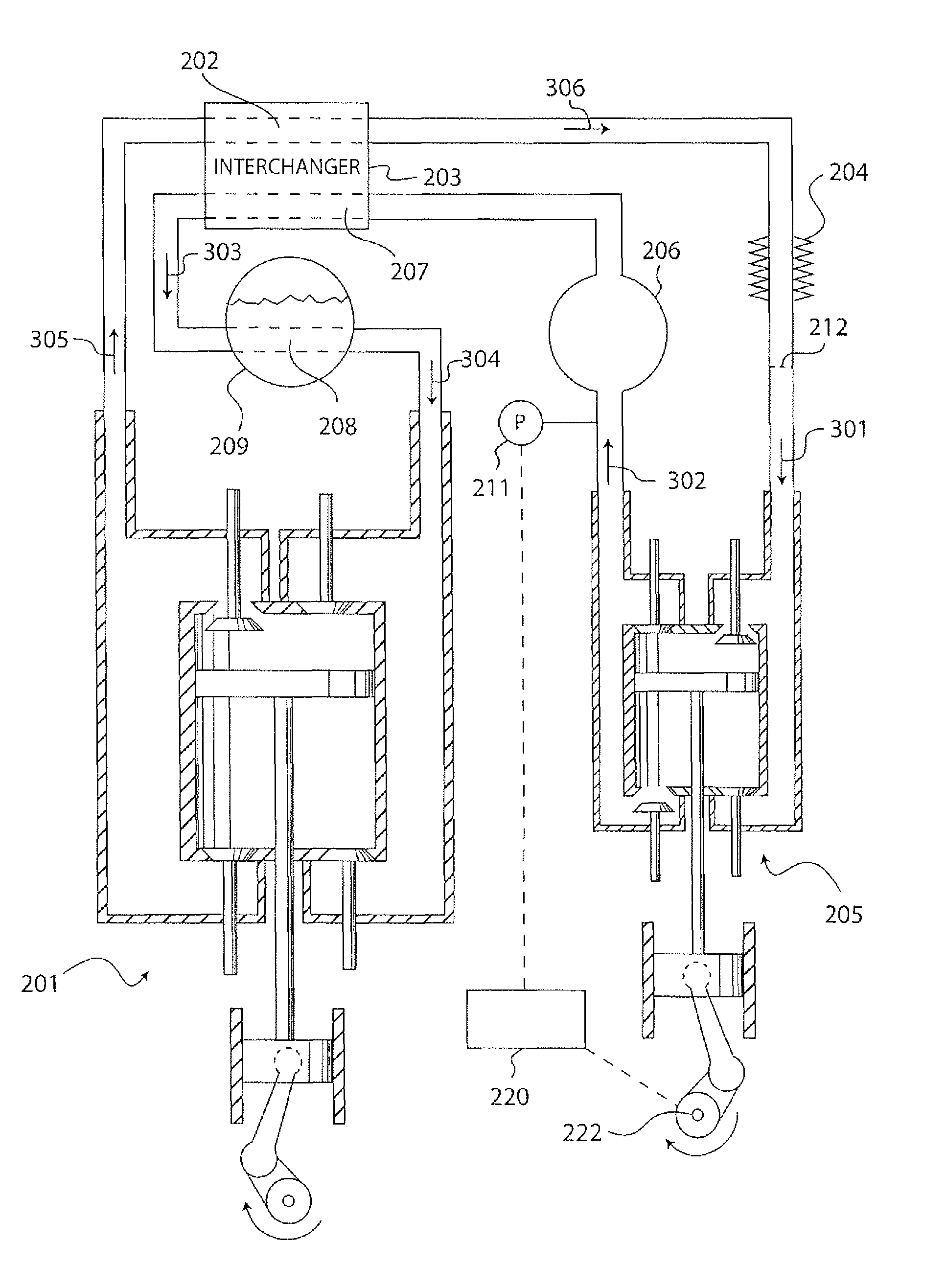
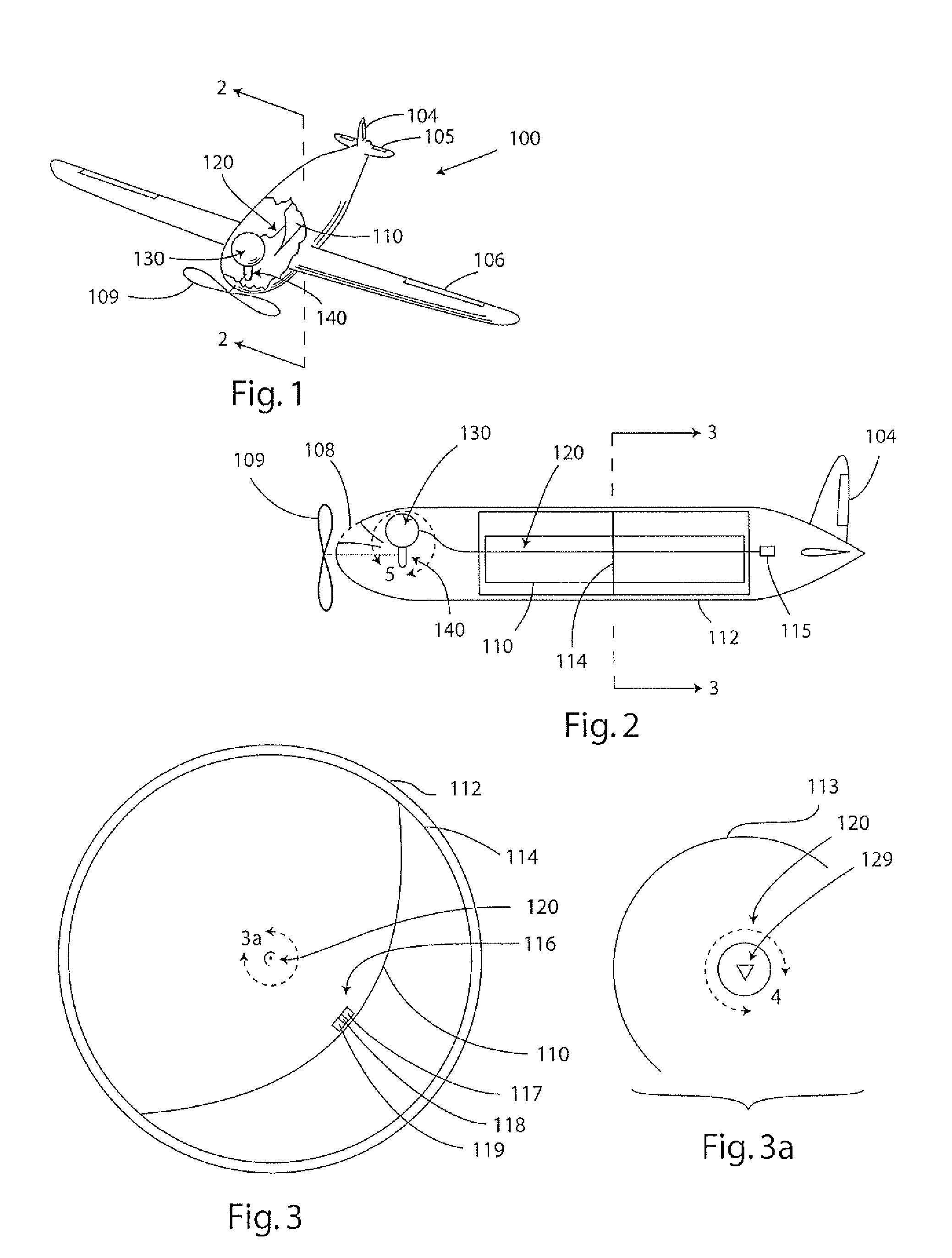
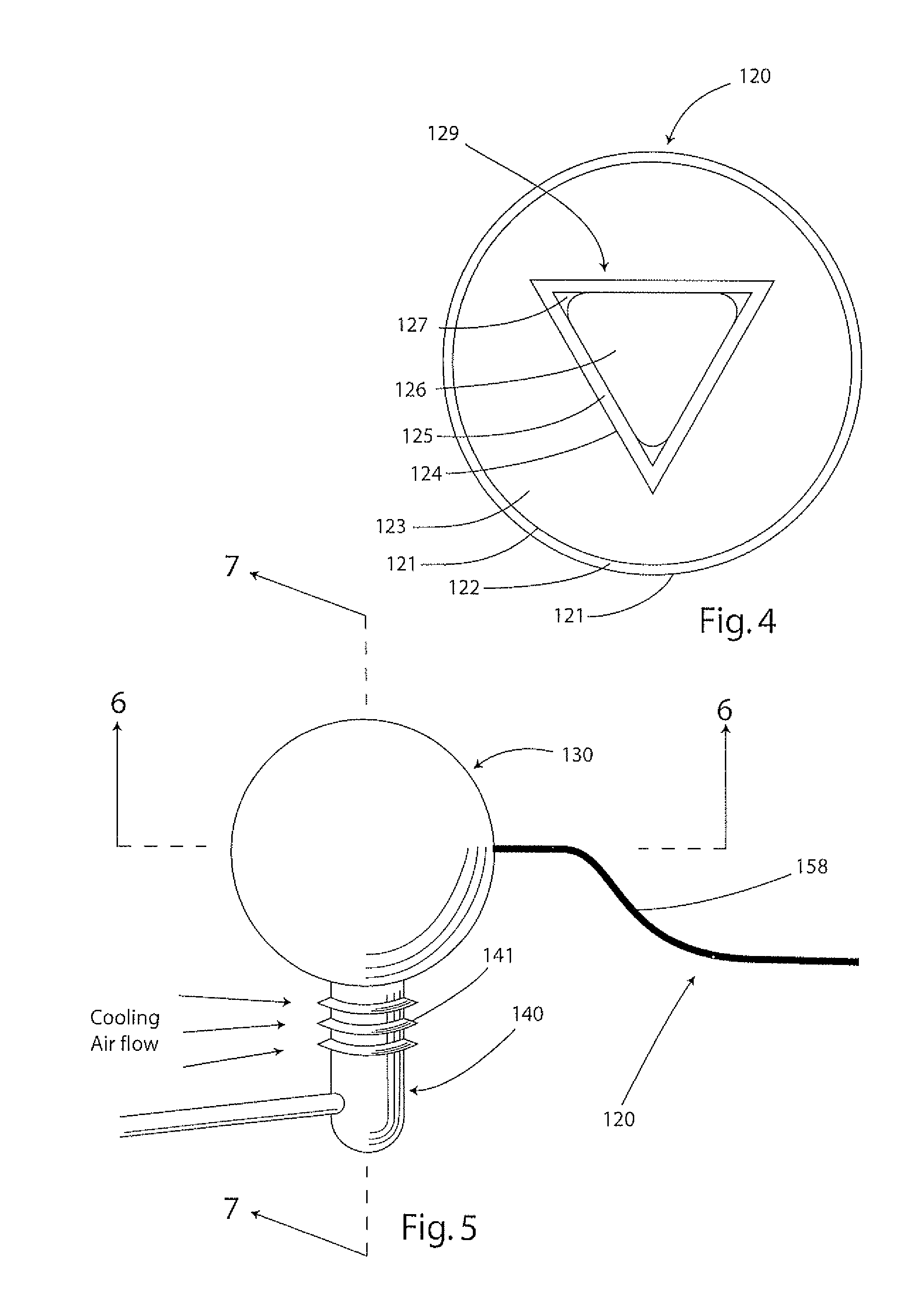
TABLE 1100Solar thermal powered aircraft102Wing103Fuselage104Rudder105Elevator106Aileron107Transmission108Cooling air inlet channel109Propeller110Concentrator mirror111Ruddervator112Transparent fuselage skin113Back-reflector114Solar concentrator support115Solar concentrator drive motor116Heliostat117Heliostat Photovoltaic A118Heliostat Photovoltaic B119Heliostat Photovoltaic C120Heat collector121Antireflection coating122Heat collector envelope123Evacuated space124Heat collector coating125Stainless steel shell126Vapor phase sodium127Liquid phase sodium128Sodium condenser129Heat pipe130Thermal battery131Highly reflective vacuum shell132MLI (Multi-layer insulation) layers of highly reflective material133LiH containment shell structure134Hydrogen& other dissociation products of LiH135Spacers between MLI layers136Lithium hydride and lithium137Lithium impervious alloy139Gold layer140Heat engine141Coolin...


PUM


Abstract

A solar thermal powered aircraft powered by heat energy from the sun. A Rankine-Brayton hybrid cycle heat engine is carried by the aircraft body for producing power for a propulsion mechanism, such as a propeller or other mechanism for enabling sustained free flight. The Rankine-Brayton engine has a thermal battery, preferably containing a lithium-hydride and lithium mixture, operably connected to it so that heat is supplied from the thermal battery to a working fluid. A solar concentrator, such as reflective parabolic trough, is movably connected to an optically transparent section of the aircraft body for receiving and concentrating solar energy from within the aircraft. Concentrated solar energy is collected by a heat collection and transport conduit, and heat transported to the thermal battery. A solar tracker includes a heliostat for determining optimal alignment with the sun, and a drive motor actuating the solar concentrator into optimal alignment with the sun based on a determination by the heliostat.

Description

I. REFERENCE TO PRIOR APPLICATIONS[0001]This application is a divisional of application Ser. No. 11 / 731,253 filed Mar. 29, 2007, now U.S. Pat. No. 7,637,457 which is a continuation-in-part of application Ser. No. 10 / 835,665 filed Apr. 30, 2004 now U.S. Pat. No. 7,270,295, entitled “Solar Thermal Aircraft,” by Charles L. Bennett, and incorporated by reference herein. Any disclaimer that may have occurred during the prosecution of the above-referenced application Ser. No. 10 / 817,107 is hereby expressly rescinded.[0002]The United States Government has rights in this invention pursuant to Contract No. W-7405-ENG-48 between the United States Department of Energy and the University of California for the operation of Lawrence Livermore National Laboratory.II. BACKGROUND OF THE INVENTION[0003]A. Technical Field[0004]This invention relates to high efficiency power plants, and in particular to a light-weight and efficient solar thermal power plant based on a Rankine-Brayton hybrid thermodynam...

Claims


Application Information

Patent Timeline
Patent Type & Authority Patents(United States)
IPC IPC(8): F01K25/02B64C39/00B64D27/24
CPCB64C39/024B64D27/023B64D27/24F01K3/004F01K7/32F01K15/02F01K25/08F03G6/065F03G6/068B64D2211/00Y02E10/46Y02T50/64Y02T50/69Y02T90/44Y02T50/50Y02T50/60Y02T90/40B64U10/25B64U50/13B64U30/40B64U30/10
Inventor BENNETT, CHARLES L.
Owner LAWRENCE LIVERMORE NAT SECURITY LLC
Why Eureka
Try Eureka