Twist lock coupling spigot

a technology of coupling spigot and twist lock, which is applied in the direction of rod connection, mechanical apparatus, building scaffold, etc., can solve the problems of significant safety risk, and achieve the effect of simple and strong mechanical connection and simple visual procedur

Active Publication Date: 2012-03-13
ATHOS CONSTR PRODS
View PDF16 Cites 73 Cited by
  • Summary
  • Abstract
  • Description
  • Claims
  • Application Information

AI Technical Summary

Benefits of technology

[0006]In the present invention, a simple twist lock arrangement is used where a locking collar includes at least one receiving slot for receiving a locking projection of an upper scaffold leg. The recessed slot is associated with a locking slot in the locking collar. When the upper scaffold leg is inserted onto the spigot, the locking projection of the upper scaffold leg passes through the receiving slot and is aligned with the locking slot when the scaffold leg is supported on the stop collar. The upper scaffold leg may then be rotated approximately 45 degrees to restrict the locking projection within the locking slot. This provides a simple and strong mechanical connection of one scaffold leg to the other. Furthermore, as the locking procedures are associated with the mounting of the upper scaffold leg on the upper portion of the coupling spigot, the workman will complete this process as it is simple and straight forward. For safety inspectors, it is a simple visual procedure to determine whether the upper scaffold leg is locked to the lower scaffold leg. Preferably, the lower scaffold leg includes a clevis pin or bolt type arrangement for securing of the coupling spigot to the lower leg.

Problems solved by technology

Although scaffolding systems are designed to allow mechanical securement of the scaffold legs one to the other (by bolts for example), this procedure is not always completed, creating a significant safety risk.

Method used


Image

  • Twist lock coupling spigot
  • Twist lock coupling spigot
  • Twist lock coupling spigot

Examples


Embodiment Construction

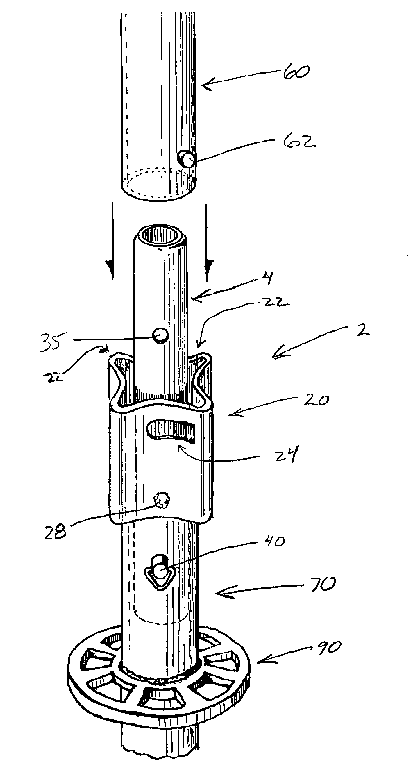
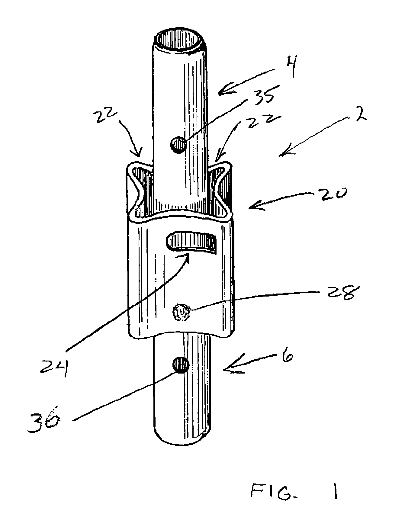
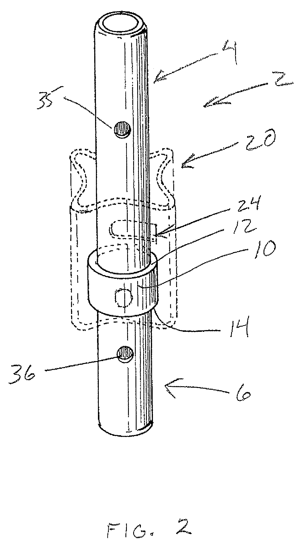
[0020]The coupling spigot 2 shown in FIGS. 1 and 2 includes an upper portion 4 and a lower portion 6 with a stop collar 10 located between and separating these portions. The upper portion 4 is received in an upper scaffold leg, and the lower portion 6 is received in a lower scaffold leg to form a strong mechanical connection. The stop collar includes an upper surface 12 for engaging the upper scaffold leg, and a lower surface 14 for engaging the lower scaffold leg.

[0021]Attached to the stop collar, as generally shown in FIG. 2, is the locking collar 20. The locking collar 20 projects above the stop collar and includes four receiving slots 22, with each receiving slot having an associated locking slot 24. The locking collar is connected to the stop collar by a series of welds shown as 28. The locking collar includes four outward projections that form the receiving slots 22. The collar between these receiving slots curves inwardly and is of reduced diameter for securement to the stop ...


PUM


Abstract

A coupling spigot for connecting two scaffold legs one atop the other is designed to use a twist lock for securing the upper scaffold leg to the coupling spigot. A locking collar is fixed to a stop collar of the spigot. The locking collar includes receiving slots for receiving locking projections provided adjacent a bottom edge of the scaffold leg. Locking slots are connected to the receiving slots whereby an upper scaffold leg may be inserted on a coupling spigot of a lower scaffold leg and retained thereon by a twist lock.

Description

FIELD OF THE INVENTION[0001]The present application relates to coupling spigots for use in association with scaffold legs, and in particular, relates to a coupling spigot having a locking collar.BACKGROUND OF THE INVENTION[0002]Most scaffolding systems include scaffold legs that are connected in an end to end manner to form an upright column. Typically, a spigot-type arrangement is used to connect a lower scaffold leg to an upper scaffold leg. In some scaffolding systems, the spigot is an integral part of the top portion of the scaffold leg often formed by seeming to reduce the diameter at the end, and the bottom portion of the scaffold leg is slightly enlarged or bell mouthed to receive the spigot. Other scaffolding systems use a separate spigot member that is inserted in a lower end of an upper scaffold leg, and a lower portion of the spigot is inserted in the end of the lower scaffold leg. Typically, the spigot is attached by a removable gravity lock pin, such as a pigtail pin, t...

Claims


Application Information

Patent Timeline
Patent Type & Authority Patents(United States)
IPC IPC(8): E04G7/00
CPCE04G7/20E04G7/22E04G7/301Y10T403/30Y10T403/551
Inventor ROGERS, PETER J.
Owner ATHOS CONSTR PRODS
Why Eureka
Try Eureka