Liquid crystal display device

a liquid crystal display and display device technology, applied in non-linear optics, instruments, optics, etc., can solve the problems of reducing the cr ratio when viewed at an oblique angle, deteriorating color reproduction at low grayscale levels, etc., to achieve high cr ratio, improve tonality, and improve color reproduction.

Active Publication Date: 2012-03-13
PANASONIC INTELLECTUAL PROPERTY CORP OF AMERICA +1
View PDF9 Cites 0 Cited by
  • Summary
  • Abstract
  • Description
  • Claims
  • Application Information

AI Technical Summary

Benefits of technology

[0019]With the present invention, it is possible to realize a brightness reduction at an oblique viewing angle during black mode. This in turn allows for the realization of a liquid crystal display device which has a high CR ratio when viewed from the front, an improved tonality when viewed at an oblique viewing angle and a high CR ratio when viewed at an oblique viewing angle.

Problems solved by technology

The problems include a significant light leakage when viewed at an oblique angle during the black mode, which in turn results in a reduction in CR ratio when viewed at an oblique angle and a deteriorated color reproduction at low grayscale levels when viewed at an oblique angle.

Method used


Image

  • Liquid crystal display device
  • Liquid crystal display device
  • Liquid crystal display device

Examples


embodiment 1

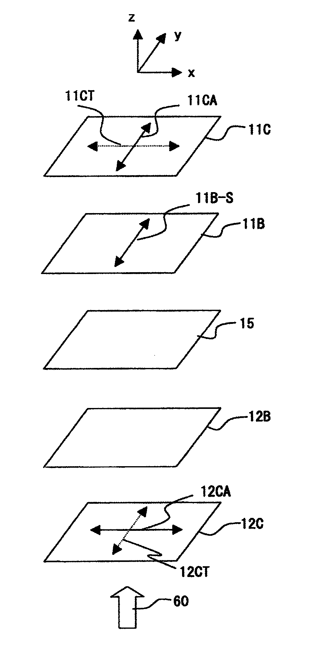
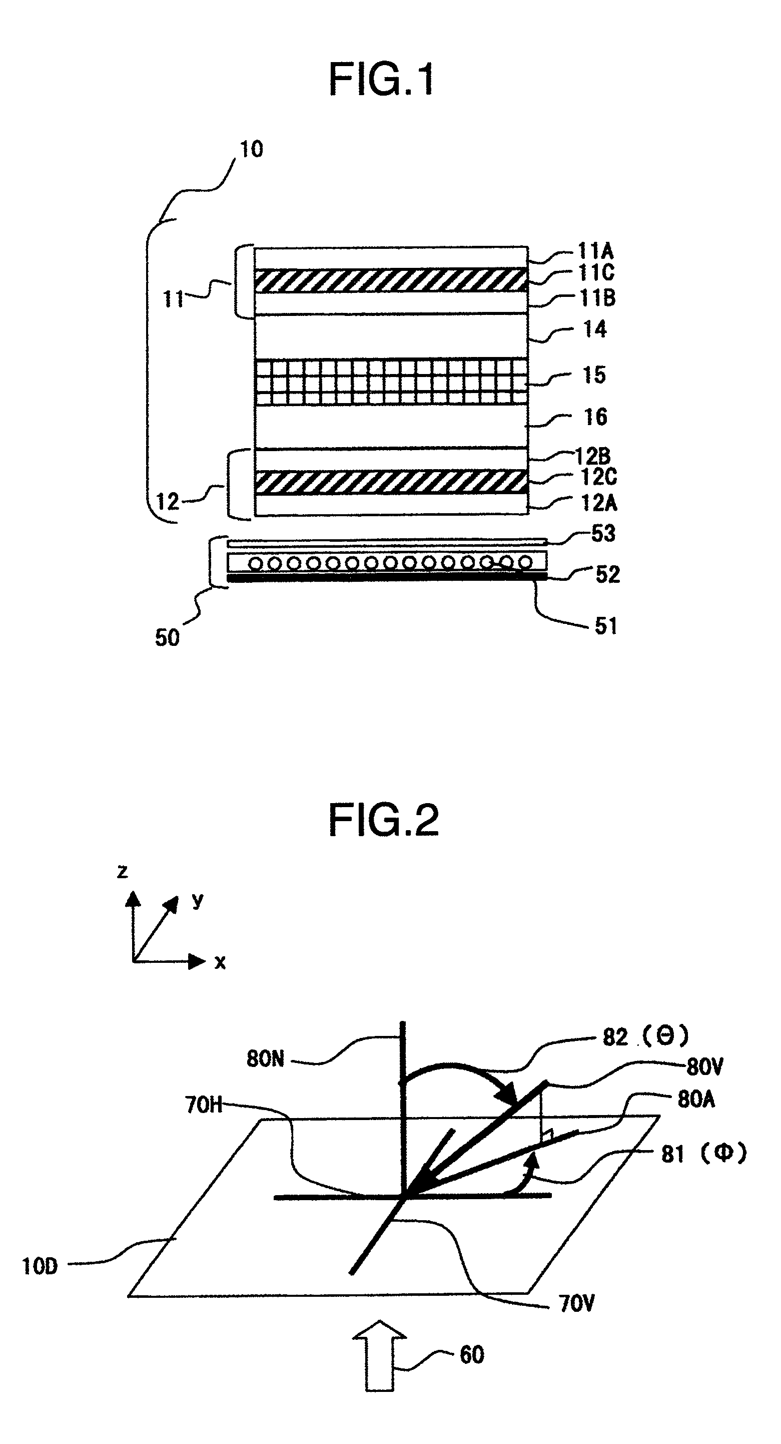
[0086]A structure of this embodiment is shown in FIG. 1 and its optical configuration in FIG. 6. When long axes of bent type liquid crystal molecules in a substrate parallel plane are aligned uniformly in an x direction, refractive indices in principal axis directions are nx=1.58, ny=1.5 and nz=1.6. The liquid crystal layer is 4.0 μm thick. The polarization plate support member 12B is formed of norbornene-type resin and has an Nz coefficient of 3.0 and a retardation of 30 nm when viewed from the front. The polarization plate support member 11B is formed of norbornene-type resin and has an Nz coefficient of 4.0 and a retardation of 40 nm when viewed from the front. During black mode, the liquid crystal layer has a uniform refractive index in the substrate parallel surface of (nx+ny) / 2=1.54 and a refractive index in substrate normal direction of nz=1.6. These calculation results are shown in FIG. 18. The abscissa represents a viewing angle (azimuth angle) at a polar angle of 60 degree...

embodiment 2

[0088]The construction of this embodiment is shown in FIG. 1 and its optical configuration in FIG. 6. When the long axes of the bent type liquid crystal molecules in the substrate parallel plane are uniformly aligned in the x direction, refractive indices in the principal axis directions are nx=1.58, ny=1.5 and nz=1.6, respectively. The liquid crystal layer is 4.0 μm thick. In this embodiment, the polarization plate support members 11B and 12B commonly use norbornene-type resin and have an Nz coefficient of 3.0 and a retardation in the front direction of 40 nm. A viewing angle dependency of the transmissivity at a viewing angle (polar angle) of 60 degrees in black mode is shown in FIG. 21.

embodiment 3

[0089]The construction of this embodiment is shown in FIG. 1 and its optical configuration in FIG. 8. When the long axes of the bent type liquid crystal molecules in the substrate parallel plane are uniformly aligned in the x direction, refractive indices in the principal axis directions are nx=1.6, ny=1.52 and nz=1.51, respectively. The liquid crystal layer is 4.0 μm thick. In this embodiment, the polarization plate support members 11B and 12B commonly use polycarbonate resin and have an Nz coefficient of −1.0 and a retardation in the front direction of 50 nm. A viewing angle dependency of the transmissivity at a viewing angle (polar angle) of 60 degrees in black mode is shown in FIG. 22.


PUM

PropertyMeasurementUnit
angleaaaaaaaaaa
“angleaaaaaaaaaa
angleaaaaaaaaaa

Abstract

The liquid crystal display device according to this invention comprises: a first substrate having a first polarization layer on a light incident side; a second substrate having a second polarization layer on a light outgoing side; a first birefringent medium disposed between the first polarization layer and the liquid crystal layer; a second birefringent medium disposed between the second polarization layer and the liquid crystal layer; a pixel electrode and a common electrode arranged on one of the first substrate and the second substrate; wherein an absorbing axis of the first polarization layer and an absorbing axis of the second polarization layer form an angle of from 88 degrees to 92 degrees; wherein the liquid crystal layer has a property that an in-plane refractive index anisotropy is induced in the liquid crystal layer by an electric field produced by the pixel electrode and the common electrode.

Description

BACKGROUND OF THE INVENTION[0001]The present invention relates to a liquid crystal display device and a liquid crystal panel and more specifically to significant improvements in a viewing angle characteristic of the liquid crystal display device that controls transmission and cutoff of light by applying an electric field to a liquid crystal layer having two-dimensional optical isotropy.[0002]Among liquid crystal display methods to improve contrast and viewing angle characteristic of a twisted nematic (TN) display system, there have been known an in-plane switching (horizontal electric field) display method (hereinafter referred to as an “IPS method”) and a multi-domain vertical alignment display method (hereinafter referred to as a “VA method”). These methods are able to make substantial improvements in viewing angle and contrast over the TN display method.[0003]However, in the IPS and VA methods since the liquid crystal layer is an optically uniaxial medium, if it is used as is, it...

Claims


Application Information

Patent Timeline
Patent Type & Authority Patents(United States)
IPC IPC(8): G02F1/1335G02F1/1343
CPCG02F1/13363G02F1/134363G02F2001/133635G02F2413/02G02F1/133635
Inventor KAJITA, DAISUKEHIYAMA, IKUOTAKEDA, SHINTARO
Owner PANASONIC INTELLECTUAL PROPERTY CORP OF AMERICA
Why Eureka
Try Eureka