Method and system for providing an energy assisted magnetic recording head in a wafer packaging configuration

a technology of energy-assisted magnetic recording and packaging configuration, which is applied in the direction of combination recording, data recording, instruments, etc., can solve the problems of reducing the size of the laser, adversely affecting the reliability of the conventional eamr disk drive, and reducing the reliability of the laser

Active Publication Date: 2012-03-13
WESTERN DIGITAL TECH INC
View PDF21 Cites 175 Cited by
  • Summary
  • Abstract
  • Description
  • Claims
  • Application Information

AI Technical Summary

Problems solved by technology

Although smaller lasers 30 might be used, such lasers are typically less reliable.
Consequently, reduc

Method used


Image

  • Method and system for providing an energy assisted magnetic recording head in a wafer packaging configuration
  • Method and system for providing an energy assisted magnetic recording head in a wafer packaging configuration
  • Method and system for providing an energy assisted magnetic recording head in a wafer packaging configuration

Examples


Embodiment Construction

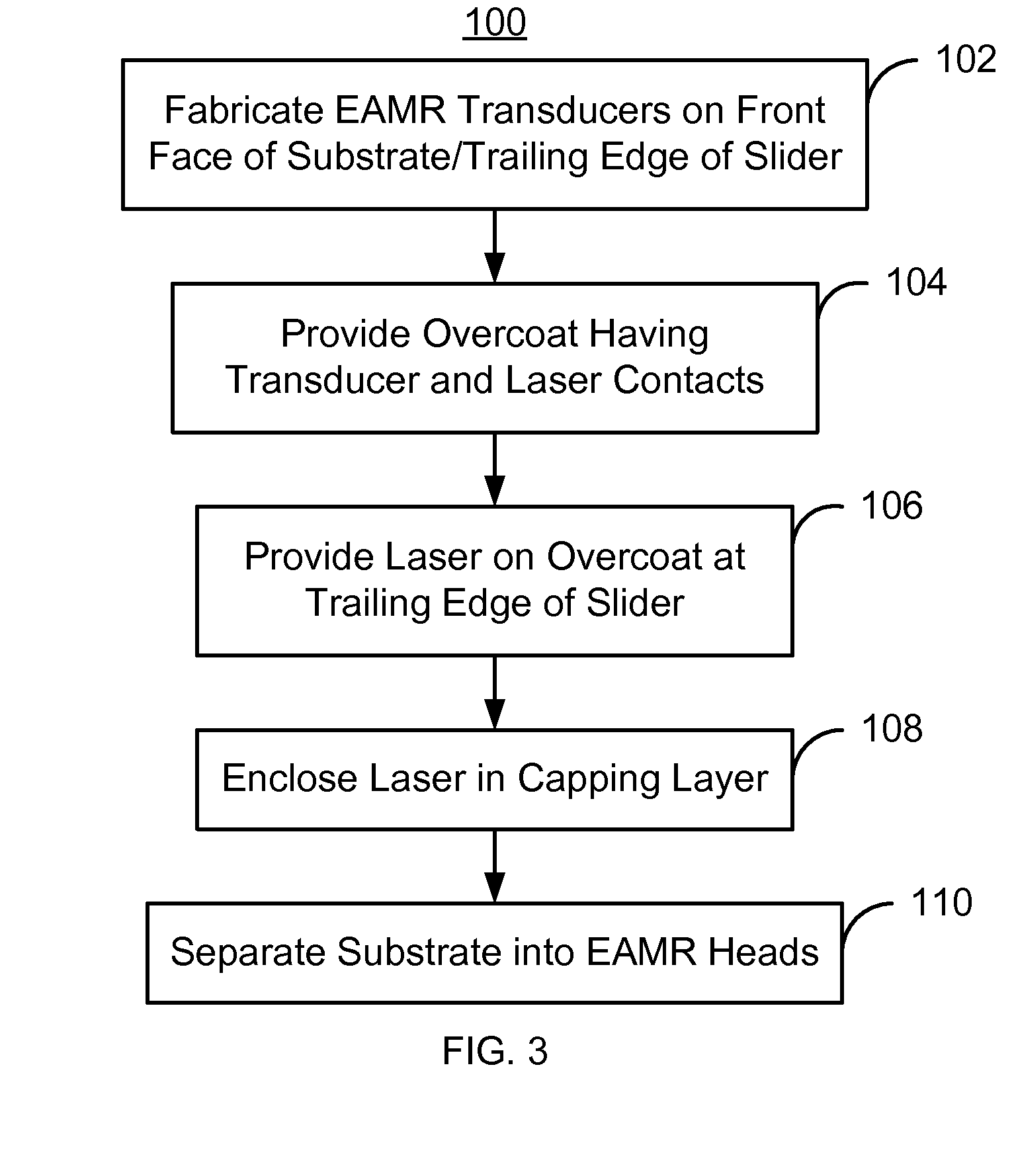
[0014]FIG. 3 is a flow chart depicting an exemplary embodiment of a method 100 for fabricating EAMR heads. Although certain steps are shown, some steps may be omitted, interleaved, performed in another order, and / or combined. The EAMR heads being fabricated may be part of merged heads, each of which includes an EAMR write transducer, a read transducer (not shown) and resides on a slider. Further, each EAMR head includes a slider having a leading edge and a trailing edge. Although termed “edges”, the leading edge corresponds to a leading surface, while the trailing edge corresponds to a trailing surface.

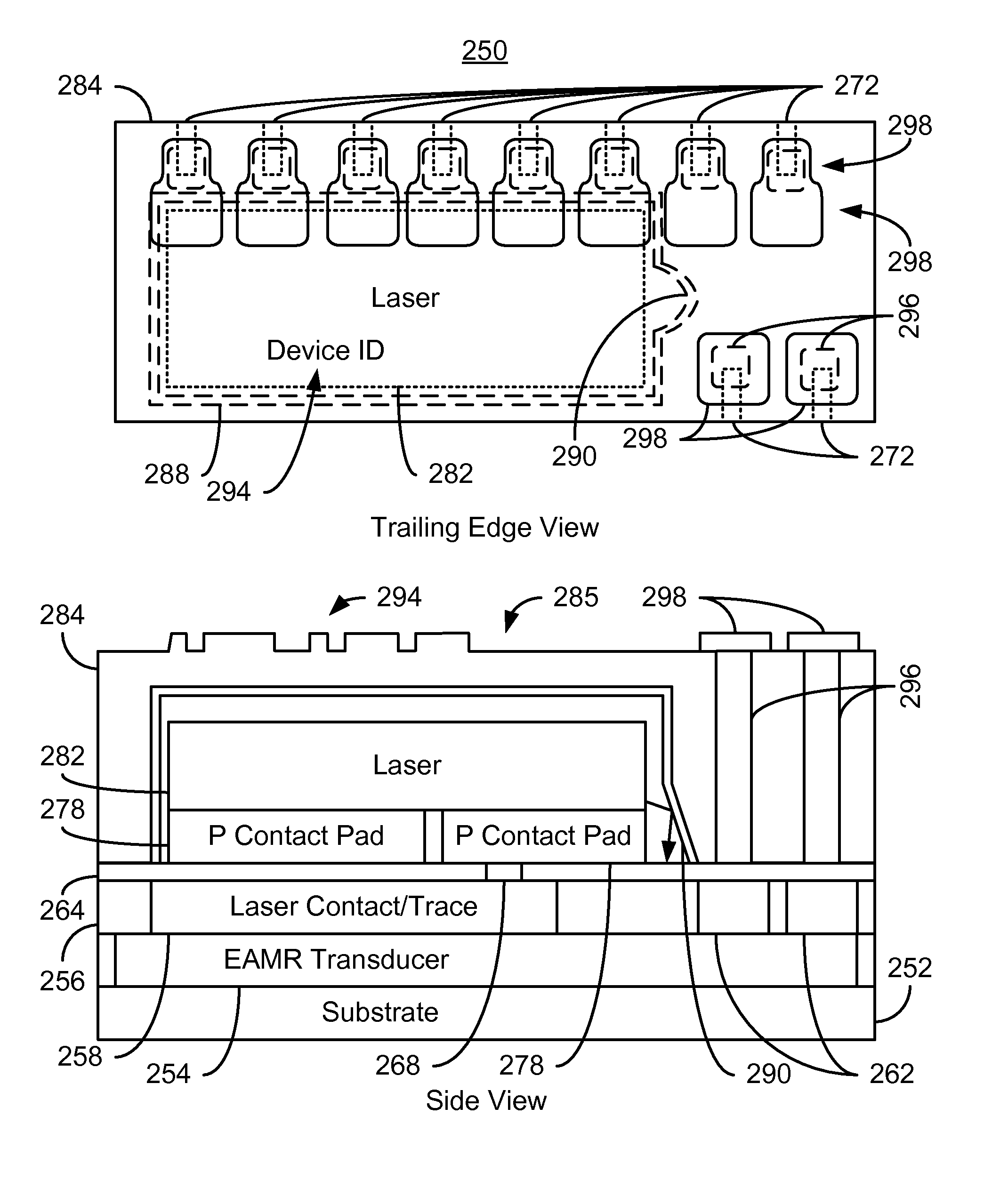
[0015]An EAMR transducer is fabricated for each of the EAMR heads, via step 102. The EAMR transducers are fabricated on the front face of a substrate. This front face corresponds to the trailing edge of the slider. Step 102 may include fabricating optics, such as gratings, waveguides, and near-field transducers (NFTs), as well as magnetic components such as poles, shields, and coils.

[...


PUM


Abstract

A method and system for providing energy assisted magnetic recording (EAMR) heads are described. The heads include sliders having leading and trailing edges. An EAMR transducer for each head is fabricated on a front face of a substrate that corresponds to the trailing edge of the slider. An overcoat layer that includes transducer and laser contact(s) is provided on the transducer. A laser for providing light to the transducer is provided on each slider. The laser is electrically coupled to the laser contact(s) and electrically insulated from at least part of the transducer contacts. The laser is enclosed in a capping layer, which has a laser-facing surface including a laser cavity, via(s), a trailing surface, and pads on the trailing surface. The laser cavity encloses the laser between the overcoat and capping layers. The via(s) provide electrical connection to the transducer contacts. The substrate is separated into the heads.

Description

BACKGROUND[0001]FIG. 1 depicts a side view of portion of a conventional energy assisted magnetic recording (EAMR) disk drive 10. The conventional EAMR disk drive 10 includes a recording media 12, a conventional slider 20, and a conventional laser diode 30 that are typically attached to a suspension (not shown). The conventional slider 20 has a leading edge 22, a trailing edge 26, and a back side 24. Although termed “edges”, the leading edge 22 and trailing edge 26 are surfaces of the slider 20. The leading edge 22 and trailing edge 26 are so termed because of the direction the conventional media 12 travels with respect to the EAMR transducer 28. Other components that may be part of the conventional EAMR disk drive 10 are not shown. The conventional slider 20 is typically attached to the suspension at its back side 24. A conventional EAMR transducer 22 is coupled with the slider 20.[0002]The laser diode 30 is coupled in proximity to the EAMR transducer 22 on the trailing edge 26 of t...

Claims


Application Information

Patent Timeline
IPC IPC(8): G11B5/02
CPCG11B5/314G11B5/6088G11B2005/001G11B2005/0021
Inventor WANG, LEI
Owner WESTERN DIGITAL TECH INC
Why Eureka
Try Eureka