Scaffold arrangement and method for repairing the edge structure of a concrete bridge

a concrete bridge and edge beam technology, applied in the direction of bridges, building scaffolds, bridge structural details, etc., can solve the problems of difficult mounting, difficult installation, and easy damage to the edge beam of concrete bridges, and achieve the effect of avoiding damage to the edge beam

Active Publication Date: 2012-03-20
MOLDTECH OY
View PDF9 Cites 6 Cited by
  • Summary
  • Abstract
  • Description
  • Claims
  • Application Information

AI Technical Summary

Benefits of technology

[0009]A further objective of the invention is to disclose a method and an arrangement which enable a considerably faster repair of the edge structure of a bridge compared to the present situation.
[0014]The invention provides the advantage that the scaffold arrangement can be mounted by working from the top of the bridge, which reduces considerably the time required for the repair work. The scaffold arrangement is quickly mounted and disassembled, saving costs and reducing the traffic disturbance. The scaffold arrangement is safe for those trafficking below. There is no disturbance for the traffic below the bridge. There is no need to drill thorough holes into the deck of the bridge that would later have to be patched up. Being steel-structured, the arrangement is strong and it can be used repeatedly several times all over again in different locations and be adapted and adjusted to be suitable for almost all existing bridges.

Problems solved by technology

The edge structure, such as the edge beam, of a concrete bridge is susceptible to damage over time e.g. due to disintegration of the concrete, providing a need to repair the edge structure.
The problem with all known scaffold arrangements is that in order to provide a sufficiently tight mounting, the mounting of the scaffold has required the formation of holes extending through the entire deck of the bridge.
Long-term work on / under the bridge with lifting machines disturbs road traffic and often also railway traffic.
Moreover, the mounting is difficult in bridges which cross waterways.
With the known methods and arrangements, for example the construction of a scaffold arrangement required for repairing the edge beam of a bridge has taken a long time.
Long mounting and repair periods hinder the traffic and increase the expenses.
Furthermore, the present scaffolds are usually made from timber, so that the scaffolds are disassembled after the work is completed, and only a portion of the stouter timber may be reused, the rest ending up on a landfill site as unserviceable.

Method used


Image

  • Scaffold arrangement and method for repairing the edge structure of a concrete bridge
  • Scaffold arrangement and method for repairing the edge structure of a concrete bridge
  • Scaffold arrangement and method for repairing the edge structure of a concrete bridge

Examples


Embodiment Construction

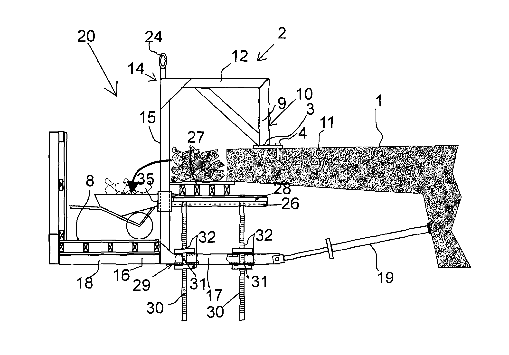
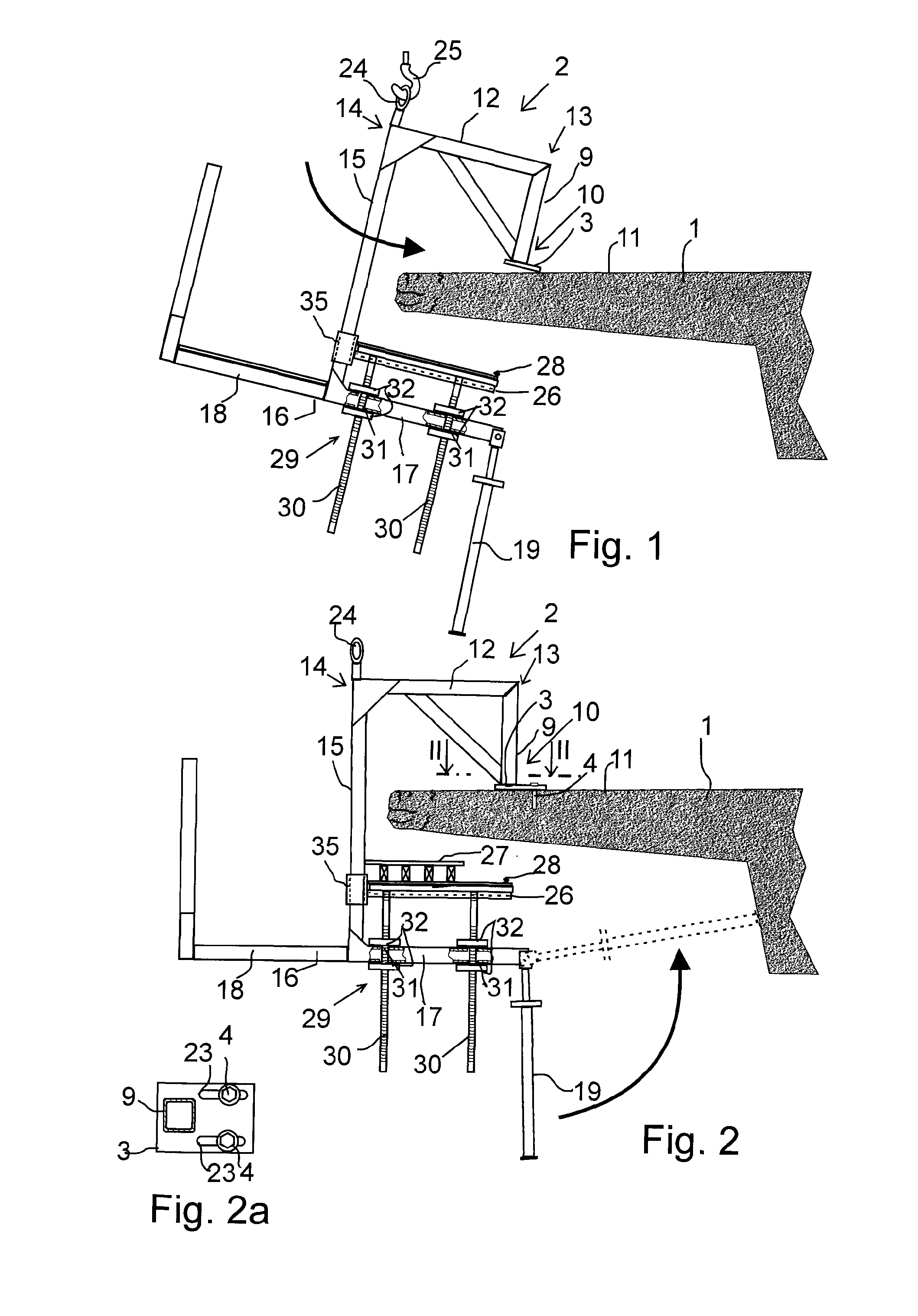
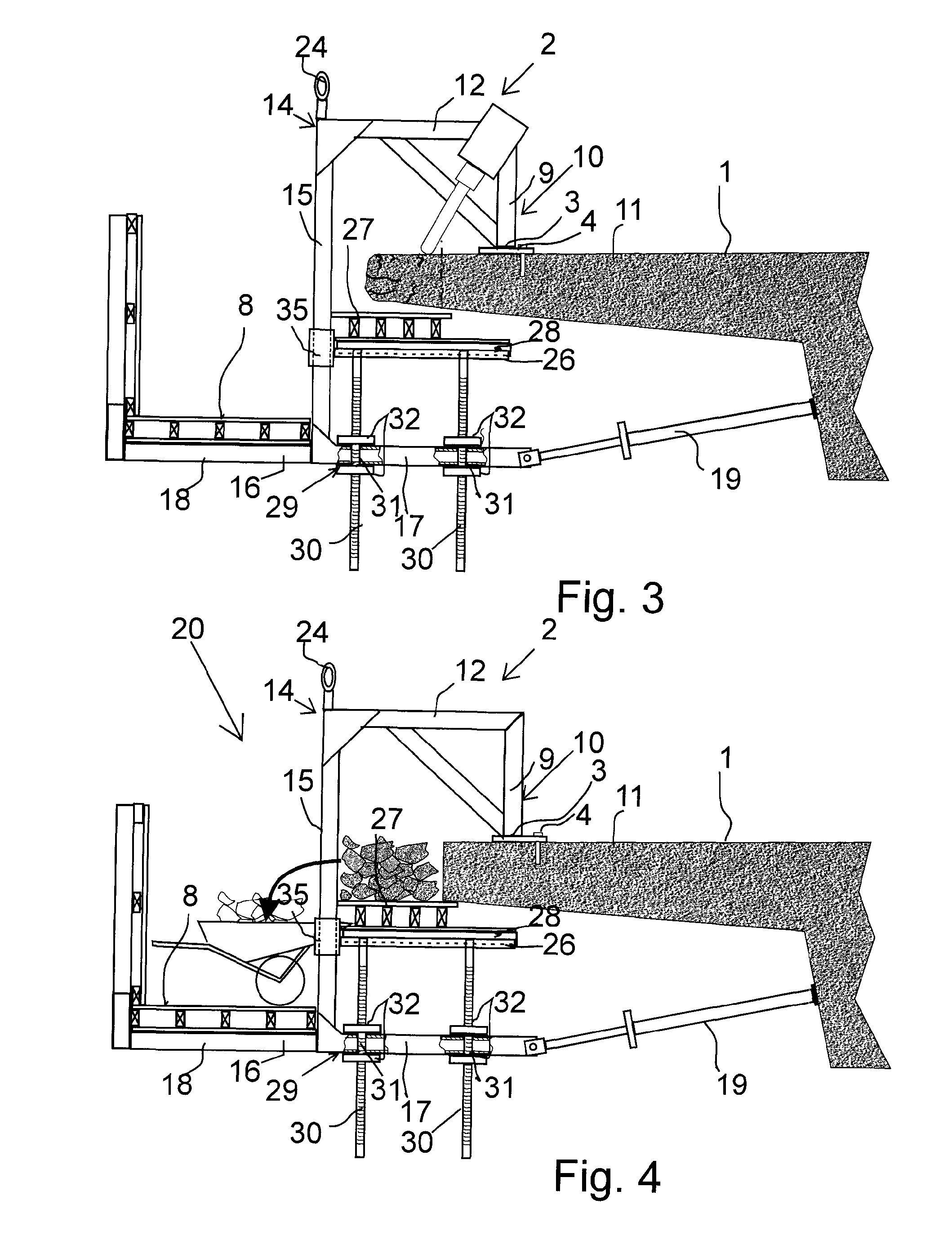
[0046]FIGS. 1-10 show the scaffold arrangement to be mounted on the upper surface of a concrete bridge in order to repair a concrete edge structure of the bridge. FIGS. 1-9 show the bridge in cross-section.

[0047]As seen from the side view 10, in the arrangement a number of bents 2 are arranged at a distance from each other along the length of the portion of the bridge that needs to be repaired. For example when renewing the edge beam of the bridge or broadening the deck of the bridge, the scaffold arrangement is usually constructed to extend over the entire length of the bridge.

[0048]FIGS. 1-9 show one bent 2. All bents 2 in the arrangement are identical.

[0049]The bents 2 are supported by support members 3, 4 onto the upper surface close to the edge of the bridge, as will be described below. Mould walls 5, 6, 7 can be supported onto the bents 2 to form a concrete casting mould for casting a new edge structure for the bridge. The scaffold arrangement also comprises an access bridge 8...


PUM


Abstract

A scaffold arrangement for repairing the edge structure of a concrete bridge. A steel-structured bent comprises a vertical beam that can be anchored by support members to the upper surface of the bridge. The vertical beam extends to a distance above the upper surface of the bridge. An upper horizontal beam is rigidly secured to the upper end of the vertical beam and the horizontal beam extends substantially transversely relative to the longitudinal direction of the bridge and over the edge of the bridge. A vertical column is secured to the end of the upper horizontal beam. The lower end of the vertical column extends down from the edge of the bridge. A lower horizontal beam is secured to the vertical column and extends in alignment with the upper horizontal beam. The lower horizontal beam comprises a first beam portion extending from the vertical column to a distance below the bridge so that mold walls can be fitted onto the first beam portion, and a second beam portion extending from the vertical column to an opposite direction relative to the first beam portion and supporting an access bridge. A longitudinally adjustable support bar is pivotally connected at one end to the first beam portion and at the other end is supportable against the lower surface of the bridge.

Description

RELATED APPLICATIONS[0001]This application claims priority and benefit from International Application No. PCT / FI2008 / 050221, filed Apr. 24, 2008, which claims priority to Finnish Patent Application No. 20070334, filed Apr. 27, 2007, the entire teachings of which are incorporated herein by reference.FIELD OF THE INVENTION[0002]The invention relates to the scaffold arrangement as defined in the preamble of claim 1. The invention also relates to the method defined in the preamble of claim 15.BACKGROUND OF THE INVENTION[0003]The edge structure, such as the edge beam, of a concrete bridge is susceptible to damage over time e.g. due to disintegration of the concrete, providing a need to repair the edge structure.[0004]In Finland, bridges are administered by e.g. Finnish Road Administration, disclosing the known methods and scaffold arrangements in their instructions concerning bridge repair (SILKO), and specifically in the SILKO instructions Betonirakenteet, Reunapalkin uusiminen, 2.211, ...

Claims


Application Information

Patent Timeline
Patent Type & Authority Patents(United States)
IPC IPC(8): E01D22/00
CPCE01D19/106E01D22/00E04G13/06E04G3/24E01D2101/26E04G13/066
Inventor JORKAMA-LOPEZ, TOMAS ALBERTOOJANTAUSTA, HANNU
Owner MOLDTECH OY
Why Eureka
Try Eureka