Hand tool

a technology of hand tools and holder, which is applied in the field of hand tools, can solve the problems of increasing the size of the holder as a whole, and the functional portion cannot be accommodated in the holder, so as to facilitate the use of the functional portion, reduce the size of the inlet opening, and facilitate the accommodation of the functional portion

Active Publication Date: 2012-03-20
KAI R&D CENT CO LTD
View PDF19 Cites 15 Cited by
  • Summary
  • Abstract
  • Description
  • Claims
  • Application Information

AI Technical Summary

Benefits of technology

[0006]Accordingly, it is an objective of the present invention to reduce the size of an inlet opening of a holder of a hand tool such as a medical edged tool by improving operation of a functional portion both in an accommodated state and a projected state.
[0016]In accordance with a second aspect of the present invention, a hand tool having a holder and a movable head portion to which a functional portion is secured is provided. The movable head portion is supported by the holder in a manner movable relative to the holder between an accommodated state, in which the movable head portion is accommodated in the holder together with the functional portion, and a projected state, in which the functional portion is projected from the holder. The position of the functional portion in the accommodated state and the position of the functional portion in the projected state are different in a longitudinal direction of the holder and in a direction perpendicular to the longitudinal direction. This structure is suitable particularly for a hand tool having a bendable functional portion. Specifically, the position of the functional portion is changed so that the functional portion is switched from the projected state, which facilitates use of the functional portion, to the accommodated state, which facilitates accommodation of the functional portion. This reduces the size of the inlet opening of the holder in which the functional portion is accommodated.

Problems solved by technology

However, if the functional portion such as the blade body is bent but an inlet opening of the holder is not sized sufficiently large for the functional portion, the functional portion cannot be accommodated in the holder.
As a result, the conventional hand tool disadvantageously has a holder with a large-sized inlet opening, which, in turn, increases the size of the holder as a whole.

Method used


Image

  • Hand tool
  • Hand tool
  • Hand tool

Examples


Embodiment Construction

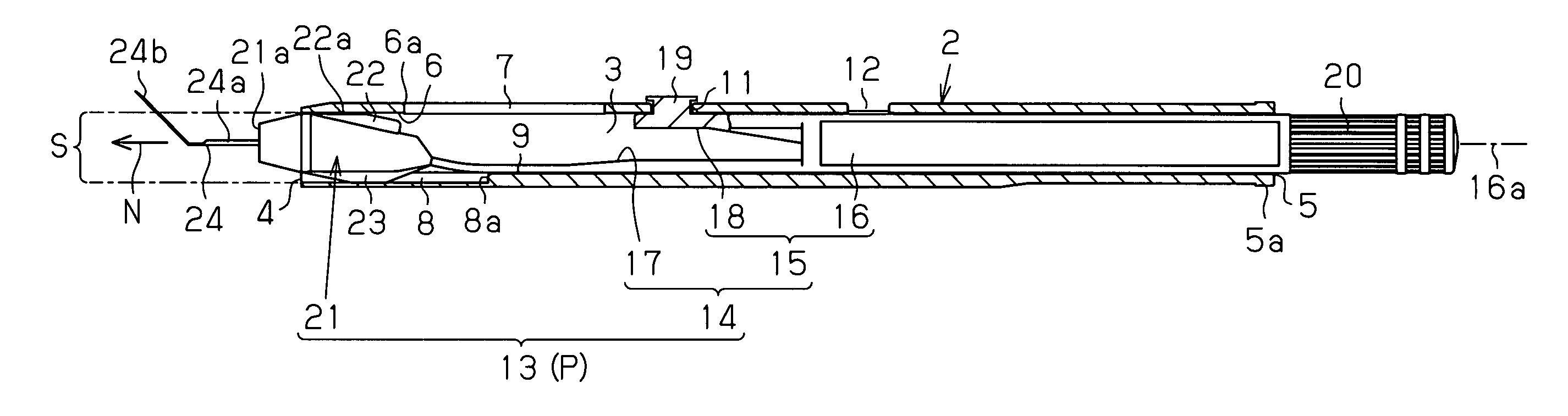
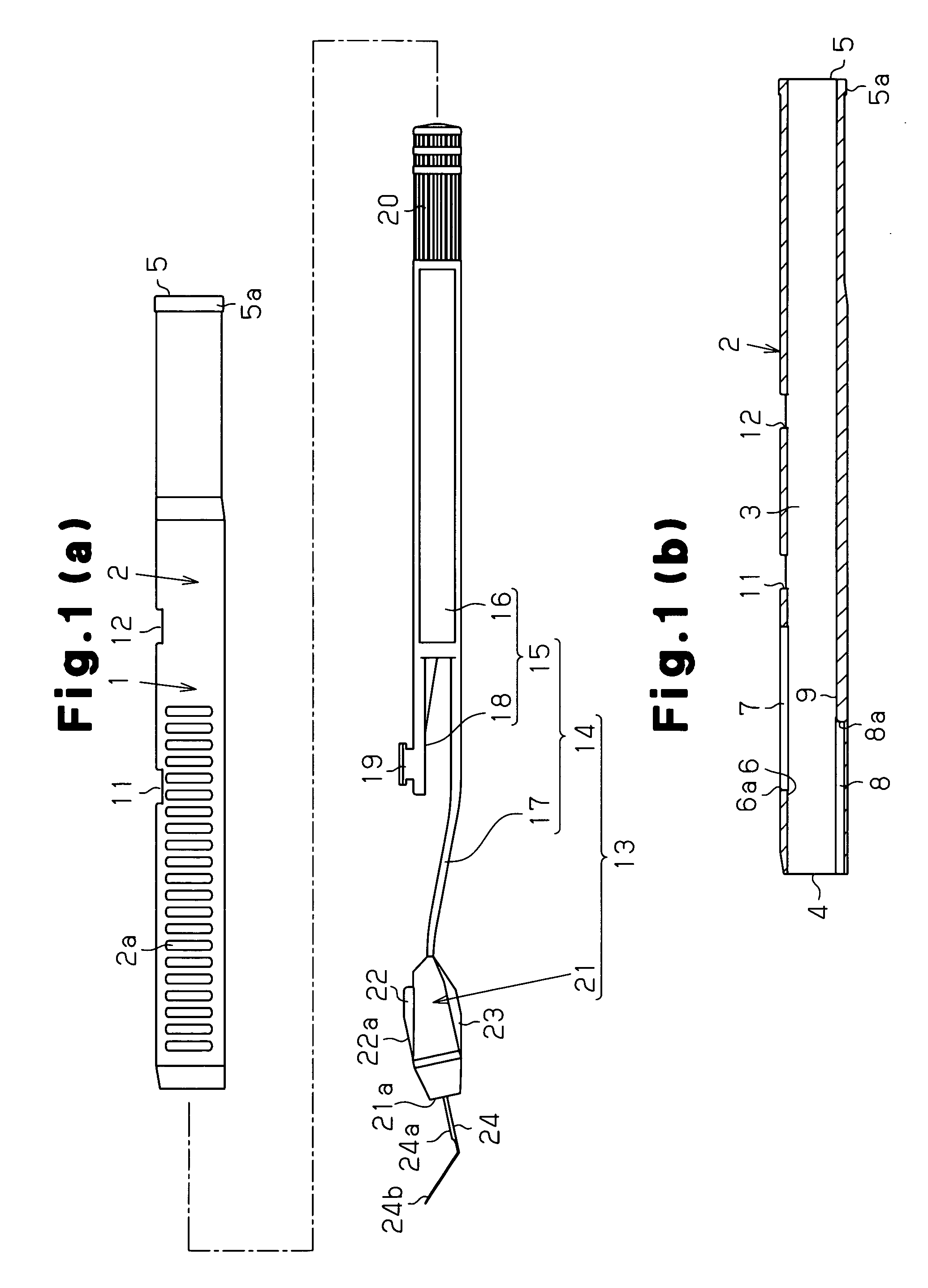
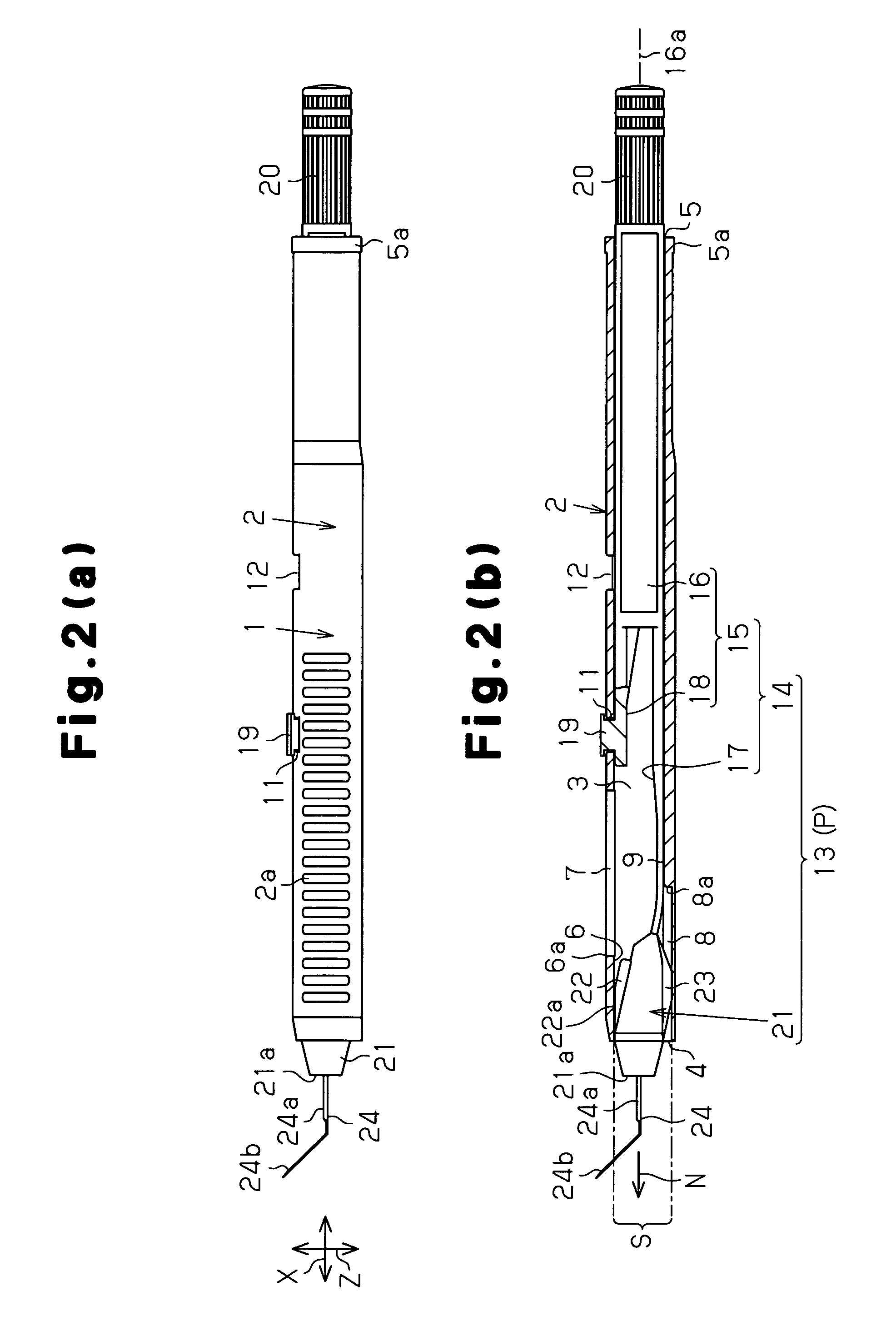
[0041]A hand tool according to one embodiment of the present invention will now be described with reference to the attached drawings. The hand tool of the embodiment is a medical edged tool. As shown in FIGS. 1(a) to 6(b), a holder 1 of the medical edged tool includes an outer circumferential wall 2 having an elongated cylindrical shape extending along the longitudinal direction X of the holder 1. An inner bore 3, which is provided in the space surrounded by the outer circumferential wall 2, is open at a front opening 4, or an inlet opening at the front end of the holder 1, and a rear opening 5, which is provided at the rear end of the holder 1.

[0042]A pressing portion 6, or a guiding / restricting portion, is provided in an upper portion of the outer circumferential wall 2 in the up-and-down direction Z of FIG. 2(a) and extends rearward from the front opening 4. A pressing escape hole 7, or an escape portion formed continuously from the pressing portion 6 through a step 6a, is formed...


PUM


Abstract

A hand tool includes a holder and a movable head portion to which a blade body is secured. The movable head portion is supported by the holder in a manner movable relative to the holder between an accommodated state Q, in which the movable head portion is accommodated in the holder together with the blade body, and a projected state, in which the blade body is projected from the holder. The orientation N of the blade body in the accommodated state Q and the orientation N of the blade body in the projected state are different from each other. This improves operation of the blade body both in the accommodated state Q and the projected state and reduces the size of a front opening of the holder to provide a compact holder of the hand tool such as a medical edged tool.

Description

CROSS REFERENCE TO RELATED APPLICATIONS[0001]This application is a U.S. national stage application of PCT / JP2007 / 064881 filed on Jul. 30, 2007, and claims priority to, and incorporates by reference, Japanese Patent Application No. 2006-0243916 filed on Sep. 8, 2006.FIELD OF THE INVENTION[0002]The present invention relates to a hand tool, or, for example, a medical edged tool, having an accommodated state, in which a functional portion such as a blade body is accommodated in a holder, and a projected state, in which the functional portion projects from the holder.BACKGROUND OF THE INVENTION[0003]Conventionally, a hand tool, which is, for example, a medical edged tool, includes a functional portion such as a blade body and a holder in which the functional portion is accommodated. The functional portion is bent and moves relative to the holder in such a manner that the hand tool is switched between an accommodated state and a projected state of the functional portion (see, for example,...

Claims


Application Information

Patent Timeline
Patent Type & Authority Patents(United States)
IPC IPC(8): B26B1/08A61B17/32
CPCA61B17/3211B26B1/08A61B2017/32113A61F9/0133
Inventor ENDO, MASAHIRO
Owner KAI R&D CENT CO LTD
Why Eureka
Try Eureka