
Mobile camera mount

a mobile camera and mount technology, applied in the field of camera mounts, can solve the problems of lack of motor vehicle mounts, lack of superior adjustability and function, and common attempts to mount cameras to the exterior of vehicles, and achieve the effect of convenient removable or permanent fixation

Active Publication Date: 2012-03-20
MALLANO DONATO
View PDF22 Cites 72 Cited by
  • Summary
  • Abstract
  • Description
  • Claims
  • Application Information

AI Technical Summary

Benefits of technology

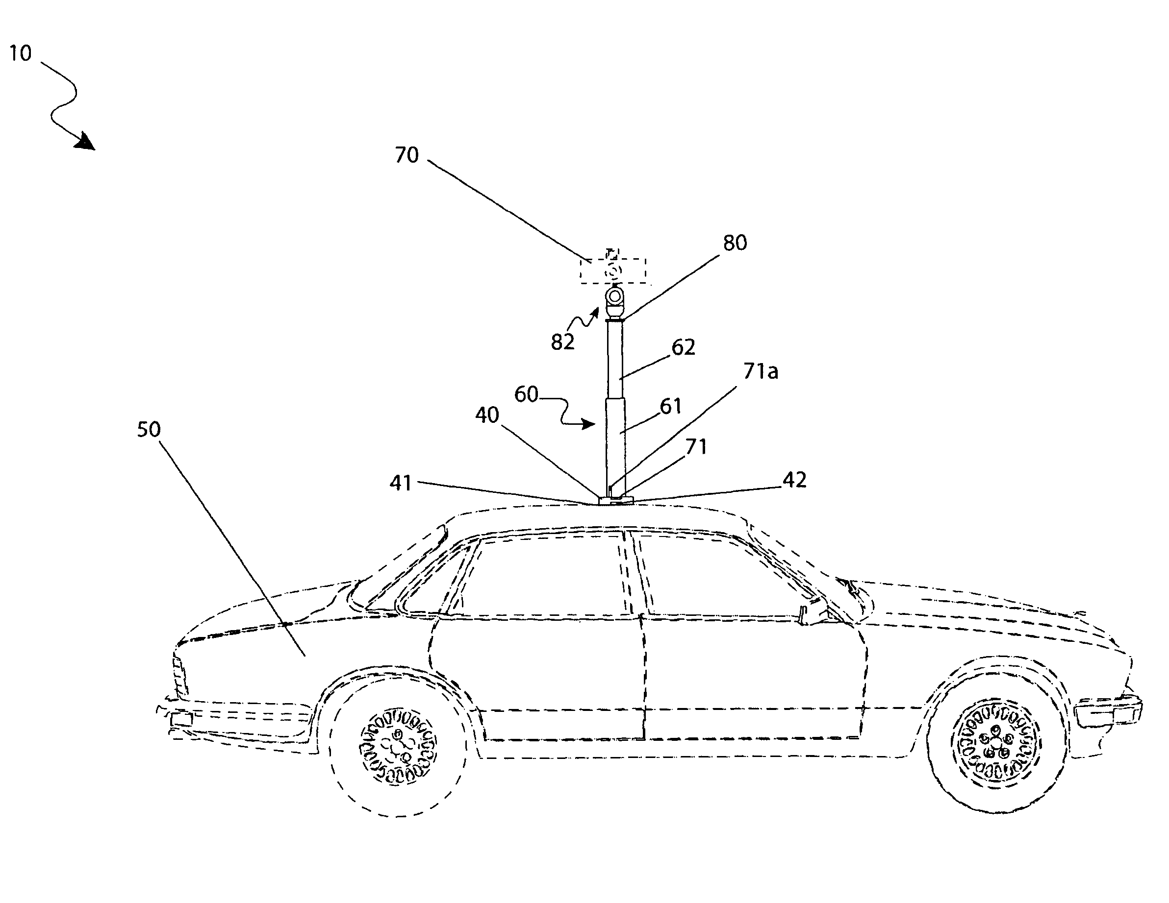
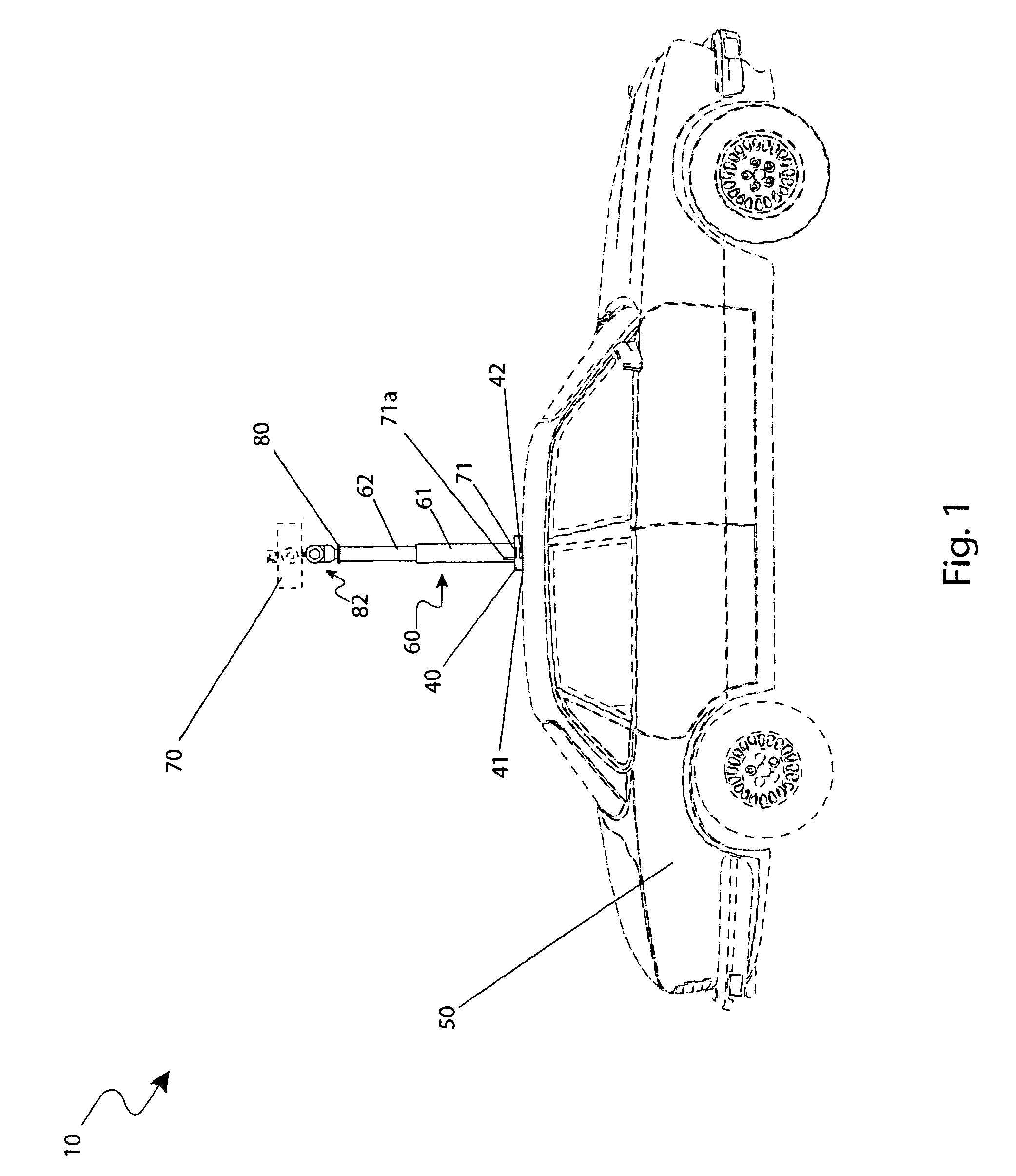
[0009]To achieve the above objectives, it is an object of the present invention to provide a mobile camera mount for a vehicle that provides a means for assisting in the photographic capture of people, environment, or other objects particularly while a user is within a vehicle.
[0011]Yet still another object of the mobile camera mount is to provide a mount that is easily removably attached or permanently attached to the roof of a vehicle that provides a means to secure the apparatus to the roof and a stable base for the attached camera system while the vehicle is in motion.
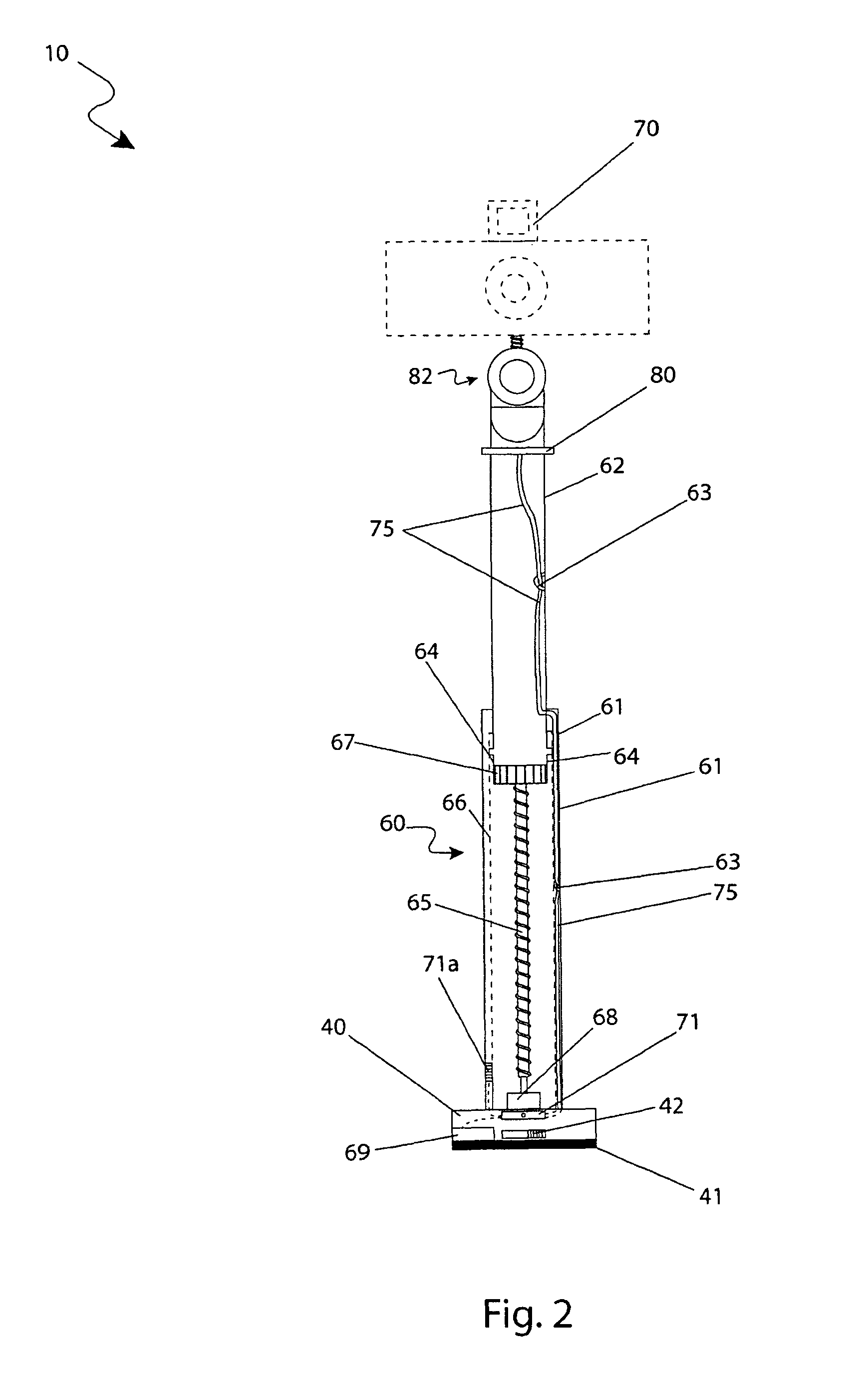
[0012]Yet still another object of the mobile camera mount is to provide a telescopic structure comprising extending members that provides a means to elevate the camera to a desired level to avoid undesirable obstructions and achieve an aerial-type photograph. The telescopic member is battery powered and motor driven comprising a lead screw and a lead screw motor which provides the height adjustability means for the apparatus.

Problems solved by technology

The most common problem encountered during any of these activities is positioning and holding the camera in a desired location.
While there are many mounts available for indoor and security use, the presence of mounts for the motor vehicle is lacking and pictures taken from the inside of a motor vehicle must contend with dirty glass, unfocused pictures, and the like.
Attempts to mount cameras to the exterior of vehicles commonly suffer from a lack of superior adjustability and function which are common among stationary camera mounts and inconvenient methods of attaching the camera mount.

Method used


Image

  • Mobile camera mount
  • Mobile camera mount
  • Mobile camera mount

Examples


Embodiment Construction

[0069]The best mode for carrying out the invention is presented in terms of its preferred embodiment, herein depicted within FIGS. 1 through 7, and in terms of its alternate embodiment in FIG. 8. However, the invention is not limited to the described embodiment and a person skilled in the art will appreciate that many other embodiments of the invention are possible without deviating from the basic concept of the invention, and that any such work around will also fall under scope of this invention. It is envisioned that other styles and configurations of the present invention can be easily incorporated into the teachings of the present invention, and only one particular configuration shall be shown and described for purposes of clarity and disclosure and not by way of limitation of scope.

[0070]The terms “a” and “an” herein do not denote a limitation of quantity, but rather denote the presence of at least one of the referenced items.

[0071]The present invention describes a mobile camer...


PUM


Abstract

A remote-controlled, roof-mounted, digital camera mount for a motor vehicle is herein disclosed. The apparatus comprises a mount system with a remote control. The mount system provides for remote control of pan and tilt functions on the mount. The remote control is provided by two (2) or more electric motors in wireless communication with said remote control located by an operator's position enabling the operator to control the positioning of the camera while operating the camera.

Description

RELATED APPLICATIONS[0001]The present invention was first described in and claims the benefit of U.S. Provisional Application No. 61 / 125,766, filed Apr. 29, 2008, the entire disclosures of which are incorporated herein by reference.FIELD OF THE INVENTION[0002]The present invention relates generally to a camera mount, and more specifically, to camera mount that is mobile and attaches to the roof of a motor vehicle.BACKGROUND OF THE INVENTION[0003]Remote control cameras are commonly used in situations where a user cannot accompany the camera due to the environment or activity which is being captured. One (1) common situation is for security and monitoring purposes. Nature and landscape photography is also becoming increasingly popular due to the ease of sharing one's photographs over the World Wide Web. With the addition of “street view” to many internet based mapping tools, users can get an on the ground snap shot of an area or even live action of events.[0004]The most common problem...

Claims


Application Information

Patent Timeline
Patent Type & Authority Patents(United States)
IPC IPC(8): G03B17/56E04H12/18
CPCB60R11/04F16M11/08F16M11/18F16M11/2021F16M11/28F16M13/022B60R2011/004B60R2011/0084B60R2011/0085B60R2011/0092F16M2200/08
Inventor MALLANO, DONATO
Owner MALLANO DONATO
Learn More