Motor, fan and manufacturing method of the same

a manufacturing method and motor technology, applied in the direction of magnetic circuit rotating parts, magnetic circuit shape/form/construction, piston pumps, etc., can solve the problems of generating noise, vibration sound generated by either the rotor holder or the impeller of the motor which are assembled with one another, and it is difficult to join an impeller made of resin material with a large-sized rotor holder

Active Publication Date: 2012-03-20
NIDEC CORP
View PDF13 Cites 5 Cited by
  • Summary
  • Abstract
  • Description
  • Claims
  • Application Information

AI Technical Summary

Problems solved by technology

Also, when the fan rotates at a low speed, other factors generate noise, such as electromagnetic sound generated by a control circuit, sliding sound generated by a bearing portion of the motor, vibration sound generated by other components of the motor.
In particular, the vibration sound generated by either a rotor holder or an impeller of the motor which are assembled with one another is noticeable.
In general, it is a difficult task to join an impeller made of a resin material with a rotor holder of a large size fan (e.g., a fan whose impeller has a diameter greater than 110 mm).
When a size of the fan increases and when a force required to press fit the rotor holder into the impeller, the cup portion may be damaged (i.e., deformed, cracked or the like).
On the other hand, when a force used to press fit the rotor holder into the impeller is compromised, the impeller may be removed easily from the rotor holder.
Therefore, the conventional method joining the rotor holder and the cup portion is problematic.
Further, since it is highly difficult to join an impeller and a rotor holder by press fitting the rotor holder into the cup portion of the impeller, large size fans include a shaft which is affixed to an impeller via a boss portion by an insert molding.
Such method, however, allows the vibrations generated by the cup portion of the impeller and that generated by other components of the motor to resonate, which, when the impeller rotates at a low speed, becomes particularly noticeable.

Method used


Image

  • Motor, fan and manufacturing method of the same
  • Motor, fan and manufacturing method of the same
  • Motor, fan and manufacturing method of the same

Examples


Embodiment Construction

A) First Preferred Embodiment

[0028]Note that in the description of preferred embodiments of the present invention herein, words such as upper, lower, left, right, upward, downward, top, and bottom for describing positional relationships between respective members and directions merely indicate positional relationships and directions in the drawings. Such words do not indicate positional relationships and directions of the members mounted in an actual device. Also note that reference numerals, figure numbers, and supplementary descriptions are shown below for assisting the reader in finding corresponding components in the description of the preferred embodiments below to facilitate an understanding of the present invention. It is understood that these expressions in no way restrict the scope of the present invention.

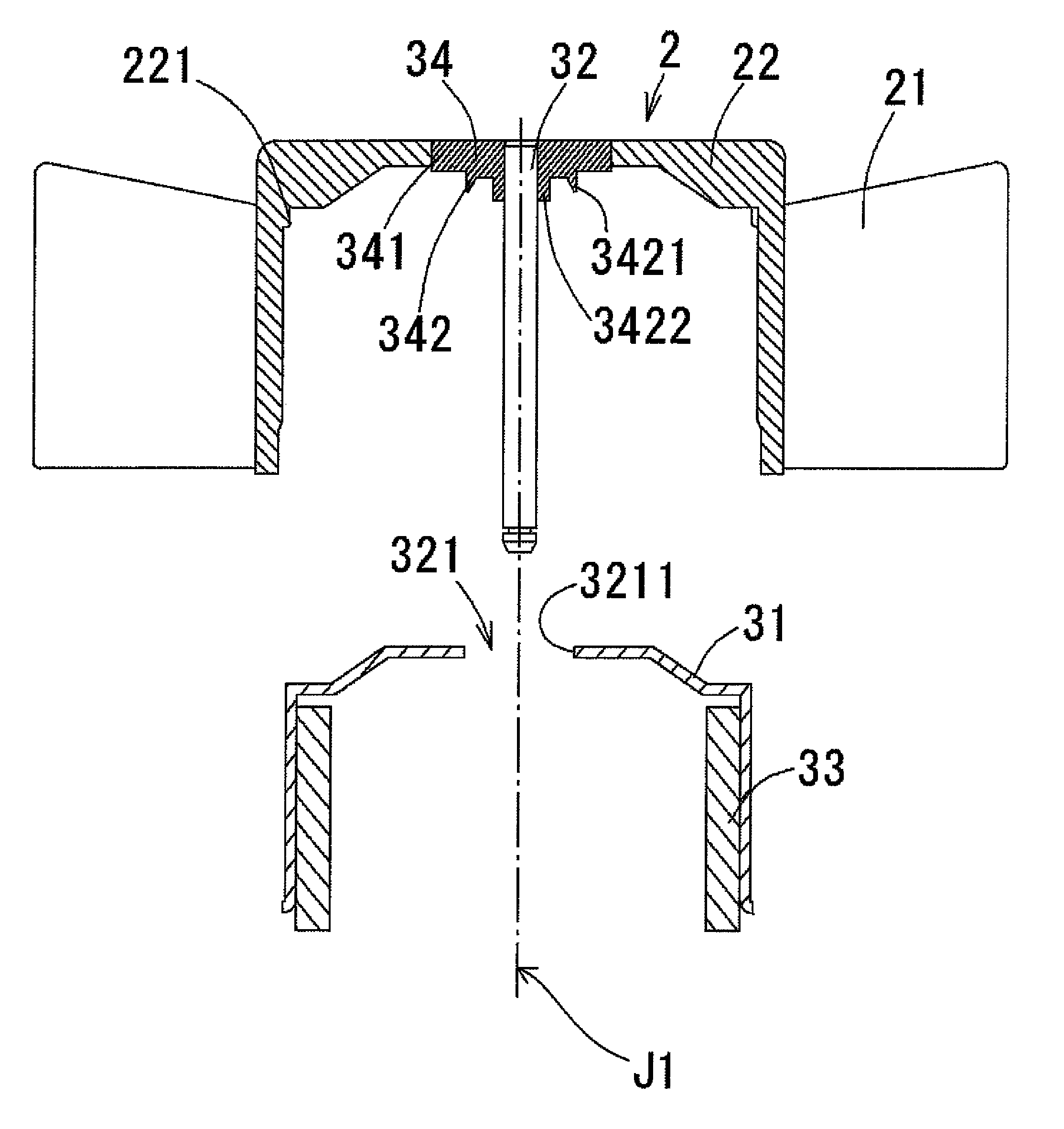
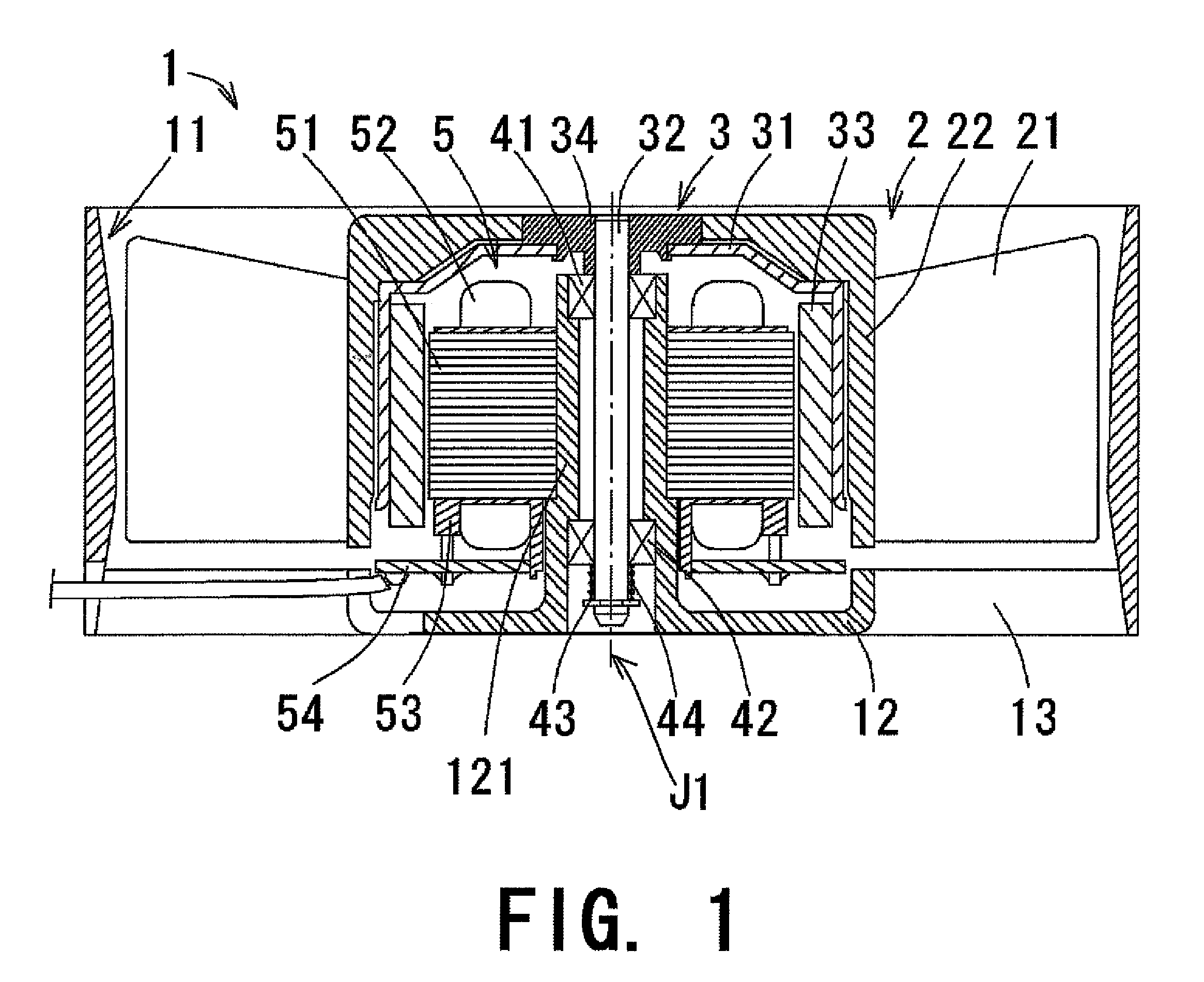
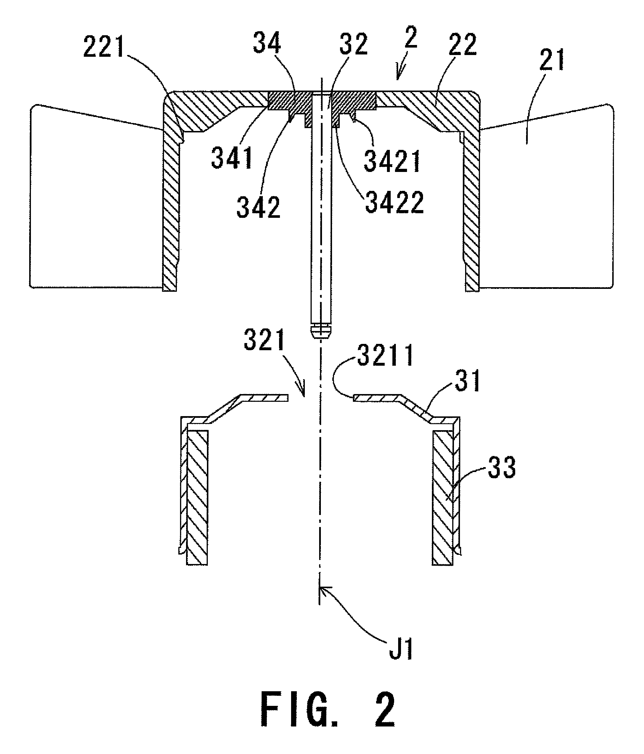
[0029]Hereinafter, a first preferred embodiment of the present invention will be described. FIG. 1 is a schematic cross sectional view of a fan 1 according to the first p...


PUM

PropertyMeasurementUnit
diameteraaaaaaaaaa
diameteraaaaaaaaaa
sizeaaaaaaaaaa

Abstract

A motor according to the present invention preferably includes a boss portion preferably includes an inner ring portion including a substantially ring shaped convex portion at an axially lower end surface thereof. The boss portion preferably includes a through hole at which a shaft is press fitted at a central portion thereof. A rotor holder including a substantially cylindrical shape includes a through hole centered about a rotary axis. The through hole and the inner ring portion of the boss portion are fitted to one another. The convex portion includes a portion plastically deformed outwardly in the radial direction to sandwich an inner circumferential surface of the rotor holder. The inner circumferential surface of the impeller cup portion includes a plurality of convex portions near an upper portion thereof. The rotor holder is press fitted into the inner circumferential surface of the impeller cup portion via the convex portions.

Description

BACKGROUND OF THE INVENTION[0001]1. Field of the Invention[0002]The present invention relates to a connection method between a rotor holder and a cup portion of an impeller of a fan.[0003]2. Description of the Related Art[0004]Conventionally, electronic devices have been generating higher amounts of heat as the number and / or capacity of their electronic components and processing units has expanded to meet current demand for higher performance devices. To this end, a fan is typically used to cool the electronic components and processor units of an electronic device. In order to achieve the characteristics (air quantity, static pressure, etc) required of the fan incorporated in the electronic devices, the fan is expected to rotate at a high speed. On the other hand, the fans incorporated in the electronic devices that are used at home and / or office environments are expected to operate quietly. To meet such expectations (i.e., reduction of high frequency noise, etc) while achieving the...

Claims


Application Information

Patent Timeline
Patent Type & Authority Patents(United States)
IPC IPC(8): F04B35/04
CPCF04D25/0613F04D29/329H02K1/30H02K7/14Y10T29/49327H02K1/2786H02K1/2791
Inventor YAMAZAKI, SHOKINAGAMATSU, HIDEKIADACHI, MASAKI
Owner NIDEC CORP
Why Eureka
Try Eureka