Methods and systems for occluding collateral flow channels in the lung

a collateral flow channel and occluding technology, applied in the field of medical methods and equipment, can solve problems such as the collapse of the channel structure, and achieve the effect of facilitating the formation of the particle circulation

Active Publication Date: 2012-03-20
PULMONX
View PDF26 Cites 16 Cited by
  • Summary
  • Abstract
  • Description
  • Claims
  • Application Information

AI Technical Summary

Benefits of technology

[0012]After occlusion of the collateral flow channels has been completed, the diseased lung segment(s) can be treated by a variety of suitable endobronchial lung volume reduction methods. Usually, volume reduction of the targeted diseased lung segment will cause a contraction of the wall which had the collateral flow channels. Such contraction will tend to collapse the channel structures over the occluding particles which have been lodged therein. Such contraction will help to anchor the particles in place and prevent their dislodgement over time. Additionally or alternatively, the particles could be coated or loaded with hydrogels and other non toxic expandable hydrogel or a combination of hydrogel and drug and non toxic sealants including, hemo glue, bone glue, tissue glue, etc as well as adhesives and / or drugs to induce permanent closure of the collateral flow channels, such as collagen and / or any derivative drug that promotes tissue growth.
[0013]In a first aspect of the present invention, methods for occluding collateral flow between adjacent lung segments comprise establishing a gas flow through the collateral flow channels in a wall between the at least two adjacent lung segments. Particles entrained in the gas flow lodge in the flow channels to occlude the collateral flow. Particles will typically have a size in the range from about 10 μm to 1000 μm, more usually from 50 μm to 500 μm. Preferably, the particles will be provided with a distribution of sizes within the above ranges in order to enhance the collection and lodging of the particles within the flow channels. In this way, flow channels having a variety of widths; lengths and geometries may be occluded.
[0017]The delivery catheters will usually have a cuff, balloon, or other occluding element near their distal ends in order to isolate the diseased or other target lung segment as the particles are being introduced. Optionally, the delivery catheter may be introduced through a separate bronchoscope or other tubular introducer which also includes a cuff, balloon, or other occlusive element in order to isolate two or more of the adjacent lung segments at a point in the feeding airways upstream from the branch between the diseased and adjacent segment(s). Use of the bronchoscope permits further control of the flow particles among the two or more lung segments.
[0019]The particles preferably have a size and composition within the ranges set forth above, and further may have a generally spherical geometry, a generally irregular geometry, or may comprise particles having both such characteristics. The catheter may comprise a primary isolation catheter which includes at least one expandable occlusion element and at least one lumen extending from a proximal end of the catheter to a point distal of the occlusion element. Usually, the catheter will have at least one additional lumen extending from the proximal end to a point proximal to the occlusion element. The use of catheters having two lumens facilitates establishing a circulation of the particles by delivering the particles through one lumen and providing a return or exhalation path for the particles through the other lumen. Optionally, a secondary isolation catheter having a central passage for coaxially receiving the primary isolation catheter may be provided. A secondary isolation catheter preferably has an expandable occlusion element on or near its distal end, thus allowing isolation of two or more adjacent lung segments at a point upstream in the branching airways of the patient.

Problems solved by technology

Such contraction will tend to collapse the channel structures over the occluding particles which have been lodged therein.

Method used


Image

  • Methods and systems for occluding collateral flow channels in the lung
  • Methods and systems for occluding collateral flow channels in the lung
  • Methods and systems for occluding collateral flow channels in the lung

Examples


Embodiment Construction

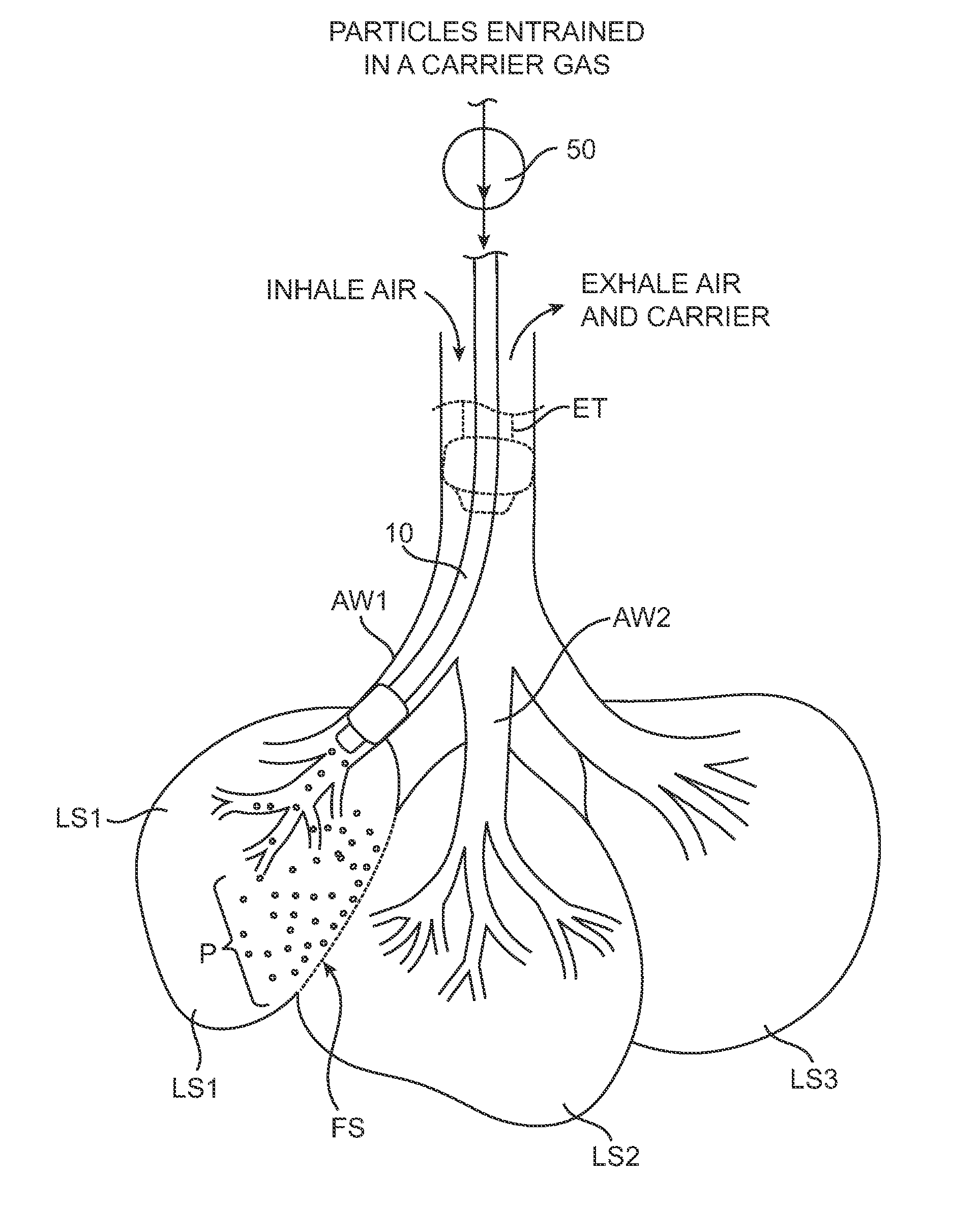
[0027]Referring now to FIG. 1, an endobronchial particle delivery catheter 10 constructed in accordance with the principles of the present invention includes an elongate catheter body 12 having a distal end 14 and a proximal end 16 with an occlusion element 15, typically an inflatable balloon or cuff near the distal end or an expandable braided balloon as disclosed in copending, commonly owned applications Ser. No. 60 / 823,734, filed on Aug. 28, 2006, and Ser. No. 60,828,496, filed on Oct. 6, 2006, the full disclosures of which are incorporated herein by reference. Catheter body 12 includes at least one central lumen or passage 18 with a distal opening 19 (FIGS. 2 and 3). A hub 20 is disposed at the proximal end 16 of the catheter body 12 and includes at least one port 17 for connection to an inflation lumen 21 which feeds an inflation medium to the expandable element 15, for sealing the distal end of the catheter within a lung airway.

[0028]In a first specific embodiment of the cathe...


PUM


Abstract

The lateral flow between adjacent lung segments is occluded by blocking collateral flow channels with particles. A gas flow is established from one lung segment through the flow channels in an intermediate fibrous septum, and out through the adjacent lung segment. Particles entrained in the gas flow become lodged in the collateral flow channels to eventually block flow.

Description

BACKGROUND OF THE INVENTION[0001]1. Field of the Invention[0002]The present invention relates generally to medical methods and apparatus. More particularly, the present invention relates to methods and apparatus for sealing collateral passages between adjacent lung segments prior to endobronchial lung volume reduction.[0003]Chronic obstructive pulmonary disease is a significant medical problem affecting 16 million people or about 6% of the U.S. population. Specific diseases in this group include chronic bronchitis, asthmatic bronchitis, and emphysema. While a number of therapeutic interventions are used and have been proposed, none are completely effective, and chronic obstructive pulmonary disease remains the fourth most common cause of death in the United States. Thus, improved and alternative treatments and therapies would be of significant benefit.[0004]Of particular interest to the present invention, lung function in patients suffering from some forms of chronic obstructive pul...

Claims


Application Information

Patent Timeline
Patent Type & Authority Patents(United States)
IPC IPC(8): A61M16/00
CPCA61M16/04A61M16/0404A61M16/0459A61M16/0479A61M16/0486A61M16/0434A61M2202/0208A61M2202/025A61M2202/0275A61M2202/0283A61M2202/064
Inventor ALJURI, NIKOLAIVENEGAS, JOSE G.NAIR, AJITPERKINS, RODNEY C.
Owner PULMONX
Why Eureka
Try Eureka