Rotational atherectomy device with fluid inflatable support elements supported by fluid bearings

a technology of atherectomy and support elements, which is applied in the field of rotational atherectomy devices, can solve the problems of affecting the normal operation affecting the function of the heart muscle, and affecting the function of the heart muscl

Active Publication Date: 2012-03-20
CARDIOFLOW
View PDF54 Cites 47 Cited by
  • Summary
  • Abstract
  • Description
  • Claims
  • Application Information

AI Technical Summary

Benefits of technology

[0029]It should be noted that throughout this specification, reference is made to “distal” and “proximal” ends and to flow of fluid in an “antegrade” and “retrograde” direction. For the avoidance of doubt, the distal end is considered to refer to the end of the device which is inserted into the vessel in the body of the patient and the proximal end is the end of the device which remains outside the body of the patient and which can be connected to a handle assembly for both rotating and longitudinally moving the drive shaft within the treated vessel. “Antegrade” flow refers to a direction of flow from the proximal towards the distal end of the device. Similarly, “retrograde” flow refers to a direction of flow in the opposite direction, i.e. from the distal towards the proximal end of the device.

Problems solved by technology

However, a disadvantage with this technique is that abraded particles can migrate along the blood vessel distally and block very small diameter vessels including capillaries of the heart muscle itself.
Clearly, the existence of particulate matter in the blood stream is undesirable and can cause potentially life-threatening complications, especially if the particles are over a certain size.
The rotational atherectomy device known from U.S. Pat. No. 5,681,336 (to Clement et al.) has a complicated construction and is difficult to manufacture on a commercial scale.

Method used


Image

  • Rotational atherectomy device with fluid inflatable support elements supported by fluid bearings
  • Rotational atherectomy device with fluid inflatable support elements supported by fluid bearings
  • Rotational atherectomy device with fluid inflatable support elements supported by fluid bearings

Examples


Embodiment Construction

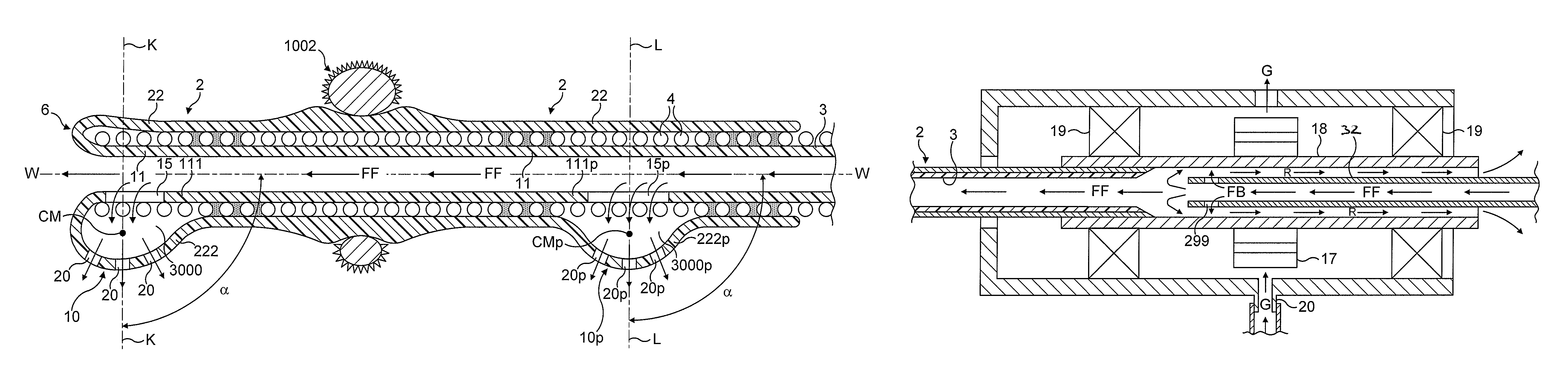
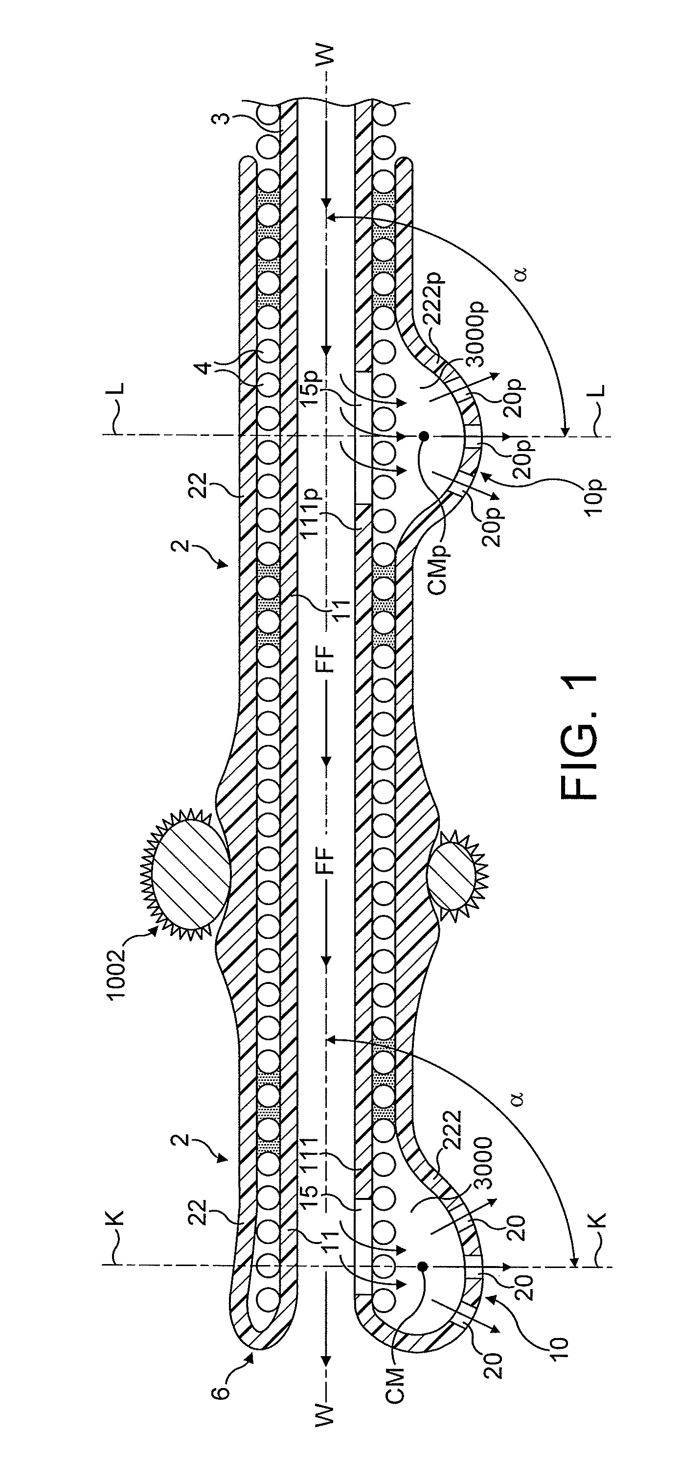
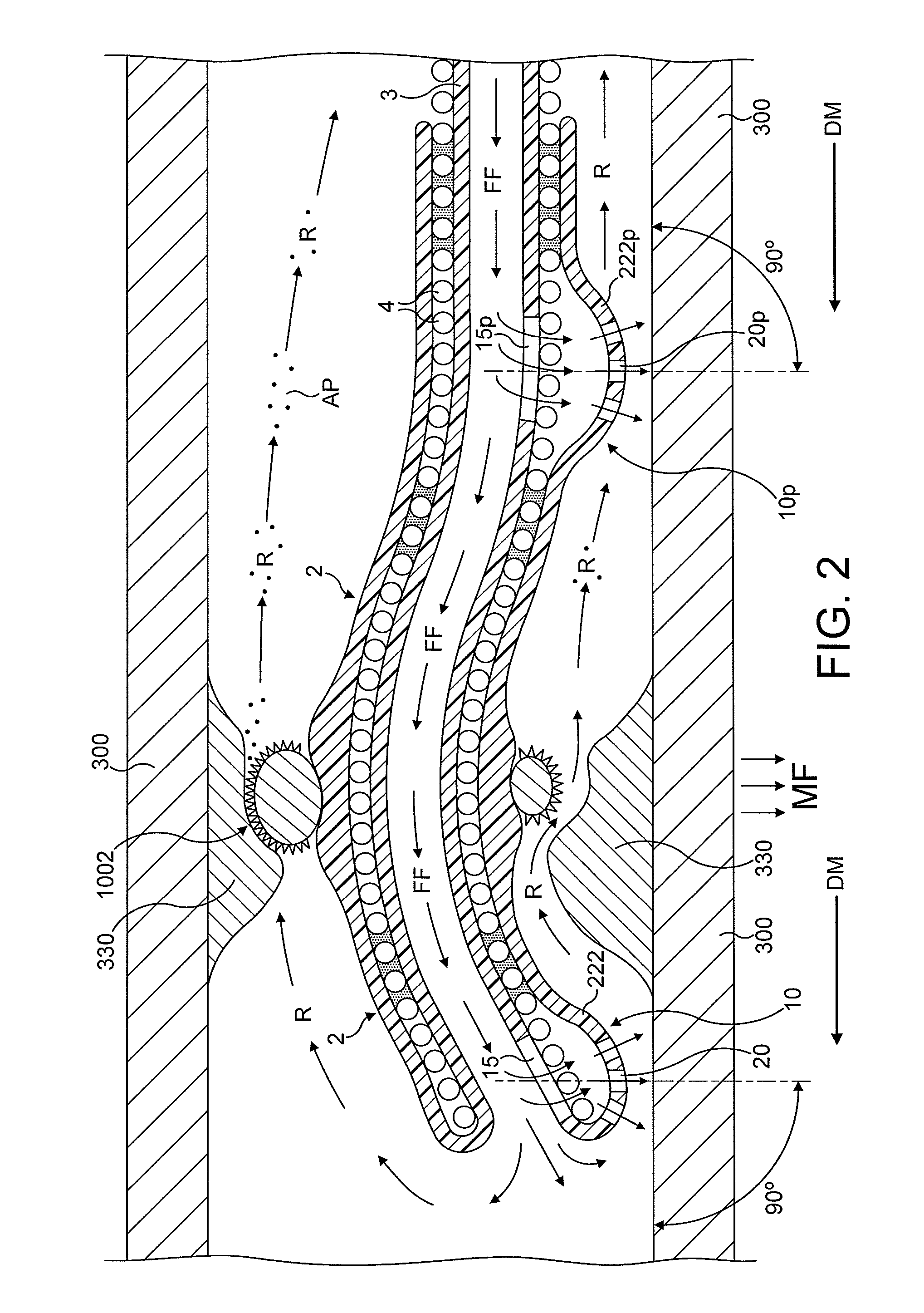
[0042]In FIGS. 1 to 12, the direction of movement of the device is indicated by arrow marked “DM”, the antegrade flow of fluid being indicated by arrows “FF” and the flow of fluid in a retrograde direction is indicated by arrows marked “R”. Abraded particles AP abraded from the stenotic lesion 330 are aspirated into a lumen of a drive shaft sheath 5000 so that the retrograde flowing fluid and the abraded particles entrained in said fluid can be removed from the treated vessel and out of the patient's body.

[0043]FIG. 1 illustrates in a longitudinal cross-section a distal portion of one preferred embodiment of the rotational atherectomy device of the invention. The rotational atherectomy device is comprised of an asymmetric abrasive element 1002 which extends around the entire circumference of the drive shaft 2 proximal to and spaced away from a distal end 6 of the drive shaft 2. The drive shaft 2 has a fluid impermeable membrane 3 which lines torque transmitting coil 4. Both the torq...


PUM


Abstract

A rotational atherectomy device for removing a stenotic tissue from a vessel of a patient is disclosed. The device comprises a rotatable, flexible, hollow drive shaft having an open distal end. The drive shaft comprising a fluid impermeable wall, an abrasive element mounted to the drive shaft proximal to and spaced away from its distal end, the fluid impermeable wall being formed from a torque transmitting coil and at least one fluid impermeable membrane which define a lumen for the antegrade flow of pressurized fluid through the drive shaft and into a distal fluid inflatable support element to inflate said fluid inflatable support element. The distal fluid inflatable support element is located at the distal end of the drive shaft and has an outer wall comprising an outflow opening located such that said outflow opening faces an inner surface of a treated vessel during rotation of the drive shaft so that a flow of fluid out of said opening forms a layer of fluid between the outer wall of the fluid inflatable distal support element and a wall of the treated vessel. The layer of fluid forming a fluid bearing between the outer wall of the rotating fluid inflated distal support element and the wall of the treated vessel.

Description

CROSS-REFERENCE TO RELATED APPLICATIONS[0001]This application is a national phase application based on PCT / EP2007 / 056500, filed Jun. 28, 2007, the content of which is incorporated herein by reference, and claims priority of GB Patent Application No. 0613980.2, filed Jul. 13, 2006, the content of which is incorporated by herein by reference.BACKGROUND OF THE INVENTION[0002]1. Field[0003]The present invention provides a rotational atherectomy device for removing a stenotic lesion from within a vessel of a patient. More specifically, the invention relates to a rotational atherectomy device for removing or reducing stenotic lesions in blood vessels such as a human artery by rotating an abrasive element within the vessel to partially or completely ablate the unwanted material.[0004]2. Description of the Related Art[0005]Atherosclerosis, the clogging of arteries, is a leading cause of coronary heart disease. Blood flow through the peripheral arteries (e.g., carotid, femoral, renal, etc.),...

Claims


Application Information

Patent Timeline
Patent Type & Authority Patents(United States)
IPC IPC(8): A61B17/22
CPCA61B17/320725A61B17/320758A61B2017/22051A61B2017/22052A61B2017/22054A61B2017/22068A61B2017/22069A61B2017/320004A61B2017/320008A61B2017/320766
Inventor SHTURMAN, LEONID
Owner CARDIOFLOW
Why Eureka
Try Eureka