Medium-voltage circuit-breaker

a circuit breaker and medium voltage technology, applied in the direction of self-interruptors, emergency protective arrangements for limiting excess voltage/current, high-tension/heavy-dress switches, etc., can solve the problems of high cost, heavy erosion of contact materials, and inevitable faults of electric power systems. , to achieve the effect of fast acting and low cos

Inactive Publication Date: 2012-03-20
ARCOLINE
View PDF18 Cites 50 Cited by
  • Summary
  • Abstract
  • Description
  • Claims
  • Application Information

AI Technical Summary

Problems solved by technology

Faults in electric power systems are inevitable.
Apart from the damages in the vicinity of the fault, owing to the effects of an electric arc, the fault currents (which are also referred to as “short-circuit currents”) can damage equipment, such as overhead lines, cables, transformers and switchgear.
This results in an intensive erosion of contact material, and consequently, in a shorter service life of the device and, what is most important, in a smaller number of fault trips.
These are the main drawbacks of the device.
A major requirement of current limiting switches is a multiple limitation of an absolute value of fault current in the protected networks.
When power consumption increases during the course of natural progress and development thus requiring additional transformers and generators, fault currents increase thus demanding a higher electrodynamic stability of the network and possibly upgrading of lines and equipment.
Drawbacks of the hybrid fault current limiter are related to kinematic complexity, high price of the components, relatively low nominal voltage (usually, up to 15 kV), and inoperative nature of the device.

Method used


Image

  • Medium-voltage circuit-breaker
  • Medium-voltage circuit-breaker
  • Medium-voltage circuit-breaker

Examples


Embodiment Construction

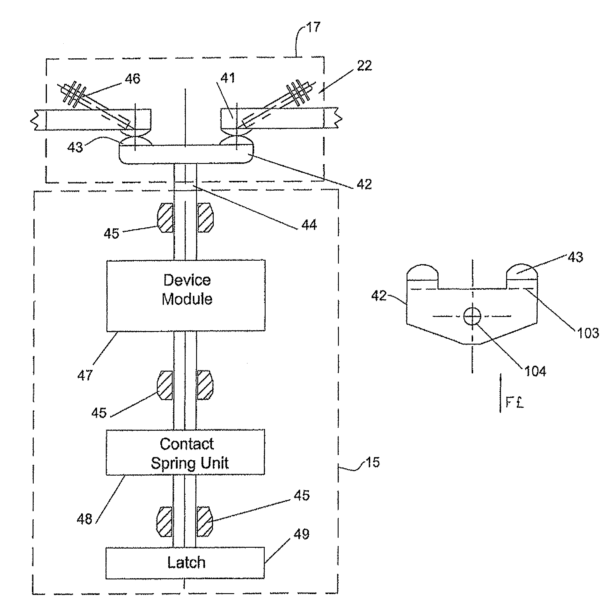
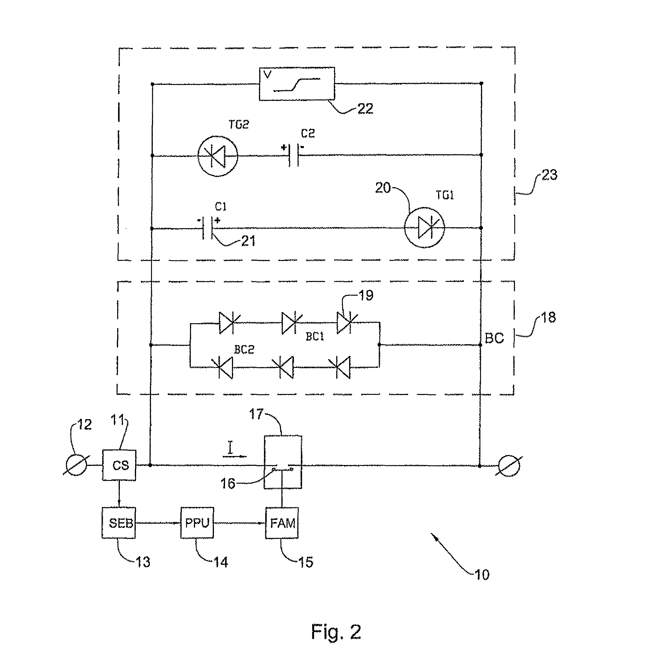
[0038]FIG. 2 is a circuit diagram showing one pole 10 of a multi-phrase circuit breaker according to an embodiment of the invention. Generally, an n-pole medium-voltage AC circuit-breaker has “n” identical independent switches, i.e. one for each phase. For example, a three-pole switch includes three equal independent phases. A current sensor 11 (CS) is connected in the AC line 12 for measuring the AC line current and feeding a signal indicative thereof to a sensor electronic board (SEB) 13. The SEB analyses the (CS) signal for fault conditions detection and in case of a fault provides a trigger signal to a pulse power unit (PPU) 14 for operating a fast acting switching mechanism (FAM) 15 that opens contacts 16 of a contactor 17 connected in the AC line. The SEB 13 also feeds the trigger signal to a thyristor bridge 18 that is coupled across the contactor 17 and that comprises two parallel branches BC1 and BC2 each having multiple series-connected thyristors 19, the thyristors in eac...


PUM


Abstract

A fast acting switching mechanism for a circuit breaker includes a drive rod articulated to a drive module and supporting at an end thereof a contact bridge having at opposite ends thereof respective moveable contacts for switchably engaging a pair of fixed contacts of the circuit breaker. A contact spring unit is operatively coupled to the drive module for applying closing pressure in the order of 200 Kg; and a latch latches the drive rod in an open or closed position after operation of the circuit breaker and prevents rebounds. The contact bridge includes a pair of side conductors supporting on upper edges thereof an armature having an exposed upper surface that supports the moveable contacts at opposite ends of the armature; and a reinforcing element inserted between the side conductors.

Description

FIELD OF THE INVENTION[0001]This invention relates to current limiting medium-voltage circuit-breakers.BACKGROUND OF THE INVENTION[0002]Faults in electric power systems are inevitable. Apart from the damages in the vicinity of the fault, owing to the effects of an electric arc, the fault currents (which are also referred to as “short-circuit currents”) can damage equipment, such as overhead lines, cables, transformers and switchgear. A fault current breaker can limit or switch of a fault current.[0003]A conventional AC fault current circuit breaker includes movable and static contacts. After a switch opening command is given, movable switch contacts move apart, thus creating an electric arc between the movable and static contacts. At a zero crossing point of the current, the arc extinguishes. It will not ignite provided that the insulation distance between the contacts is large enough to rule out. any breakdown of the dielectric between the contacts. If this distance is too small, t...

Claims


Application Information

Patent Timeline
Patent Type & Authority Patents(United States)
IPC IPC(8): H01H3/00H01H75/00H01H33/34H01H67/02
CPCH01H73/045H01H1/20H02H9/02
Inventor ONUFRIYENKO, YURIYULANOVSKY, EDUARDYEGER, DOVGOFMAN, YEFIM
Owner ARCOLINE
Why Eureka
Try Eureka