Single chip red, green, blue, distance (RGB-Z) sensor

a sensor and single chip technology, applied in the field of solid-state sensors, can solve the problems of large image artifacts, difficult to achieve in practice, and no useful depth information, and achieve the effect of rapid identification

Active Publication Date: 2012-03-20
MICROSOFT TECH LICENSING LLC
View PDF32 Cites 59 Cited by
  • Summary
  • Abstract
  • Description
  • Claims
  • Application Information

AI Technical Summary

Benefits of technology

[0012]The present invention provides a sensor that includes an array region of high resolution pixel detectors that are responsive to wavelengths in a first spectral band (such as RGB wavelengths) used to generate an image that preferably is an RGB image, and that also includes an array region of typically lower resolution pixel detectors that are responsive to wavelengths in a second spectral band (preferably but not necessarily NIR) used to acquire Z data. If desired, wavelengths of the second spectral band (used to acquire Z data) may overlap with wavelengths of the first spectral band (used to acquire an RGB image.) It is desired to acquire a good resolution RGB image of a target object a distance Z away, and to also use Z data to rapidly identify what and where the target object is.
[0016]Output from even a relatively low resolution pixel detector array acquiring Z data using preferably NIR wavelengths may be used to determine size, distance Z to the target object, and target object velocity ΔZ / Δt. The Z data aids in rapidly identifying a target object imaged by the preferably RGB array.

Problems solved by technology

While such sensors can provide a color (RGB) or gray scale (BW) image, they provide no useful depth information.
But this goal is difficult to attain in practice because pixel detectors used to capture Z-data at IR wavelengths are commonly much larger in area than pixel detectors responsive to RGB wavelengths.
If a single array were fabricated to simultaneously use RGB pixel detectors and Z pixel detectors, the presence of the large sized Z pixel detectors in a high density array of much smaller sized RGB pixel detectors would cause large image artifacts that could degrade the quality of a resultant RGB image.
In practice, CMOS fabrication does not presently implement such bandpass filtering for the Z pixels, especially with desired narrow band characteristics that may be on the order of 50 nm or less.

Method used


Image

  • Single chip red, green, blue, distance (RGB-Z) sensor
  • Single chip red, green, blue, distance (RGB-Z) sensor
  • Single chip red, green, blue, distance (RGB-Z) sensor

Examples


Embodiment Construction

[0025]Reference will now be made in detail to the preferred embodiments of the invention, examples of which are illustrated in the accompanying drawings. While the invention will be described in conjunction with the preferred embodiments, it will be understood that they are not intended to limit the invention to those embodiments. On the contrary, the invention is intended to cover alternatives, modifications and equivalents, which may be included within the spirit and scope of the invention as defined by the appended claims.

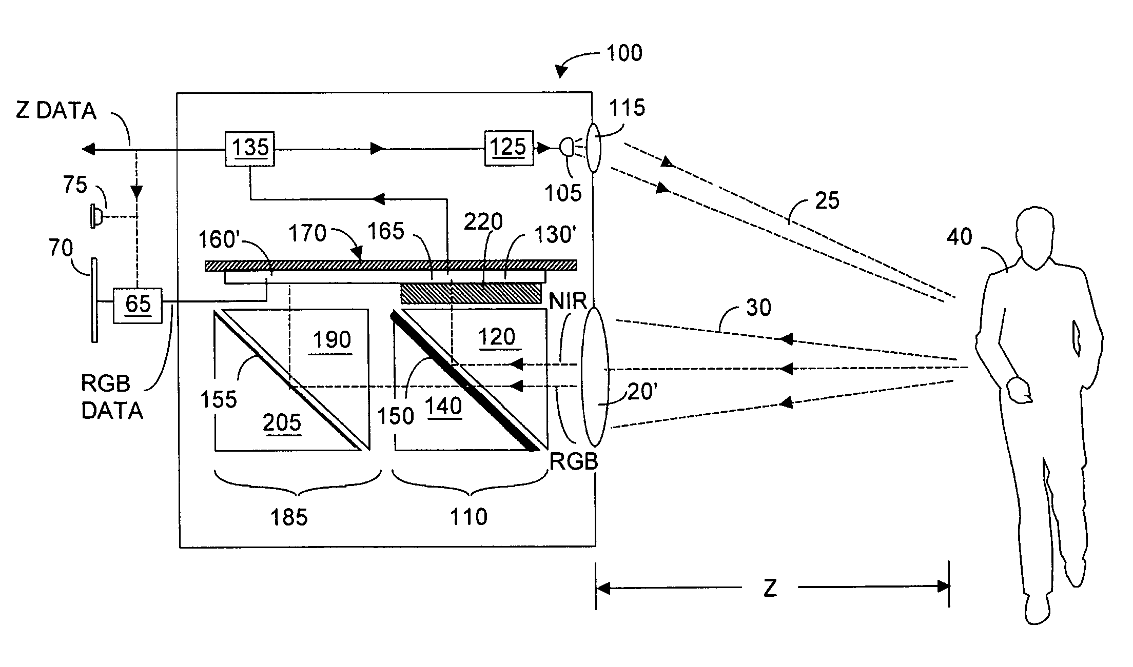
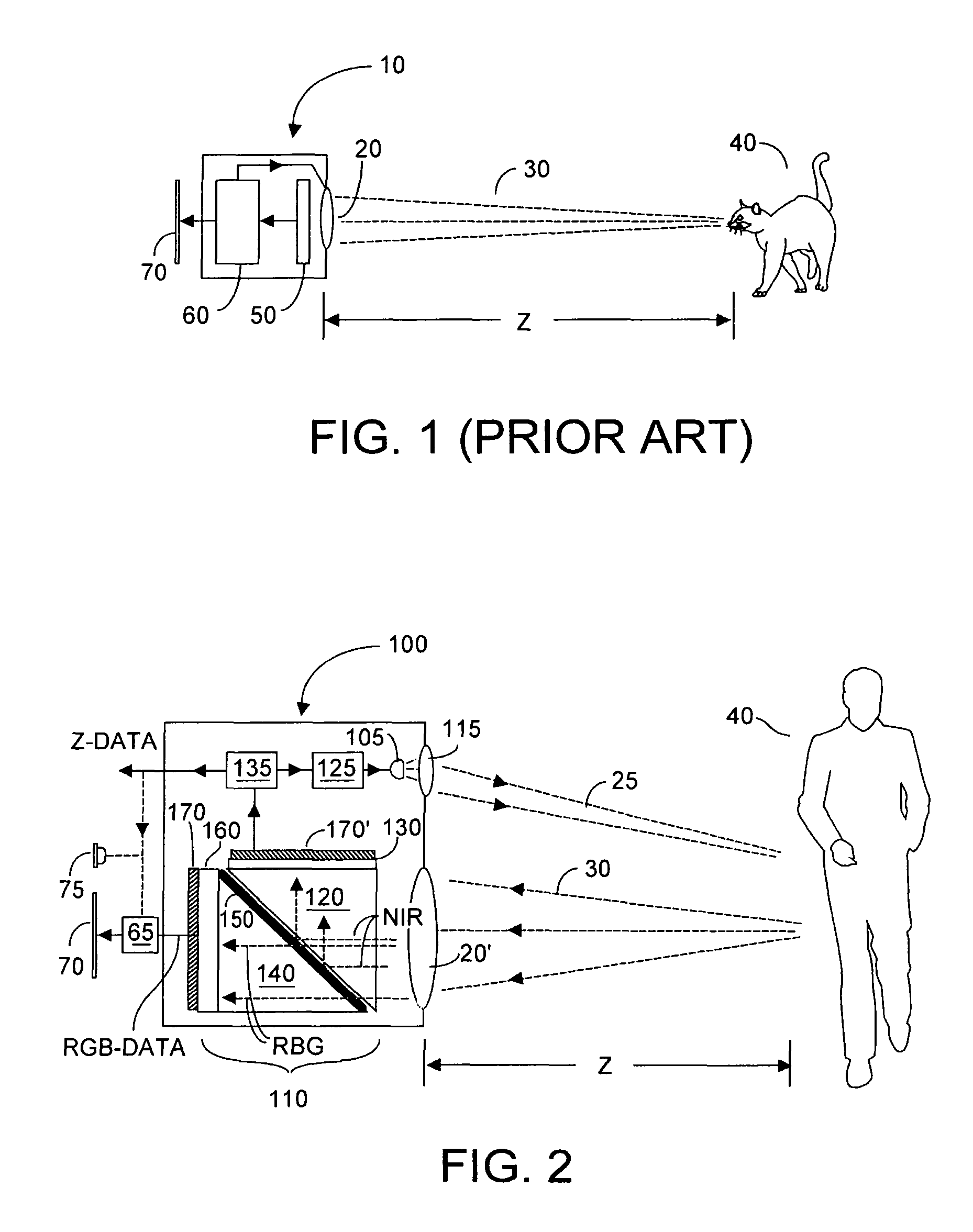
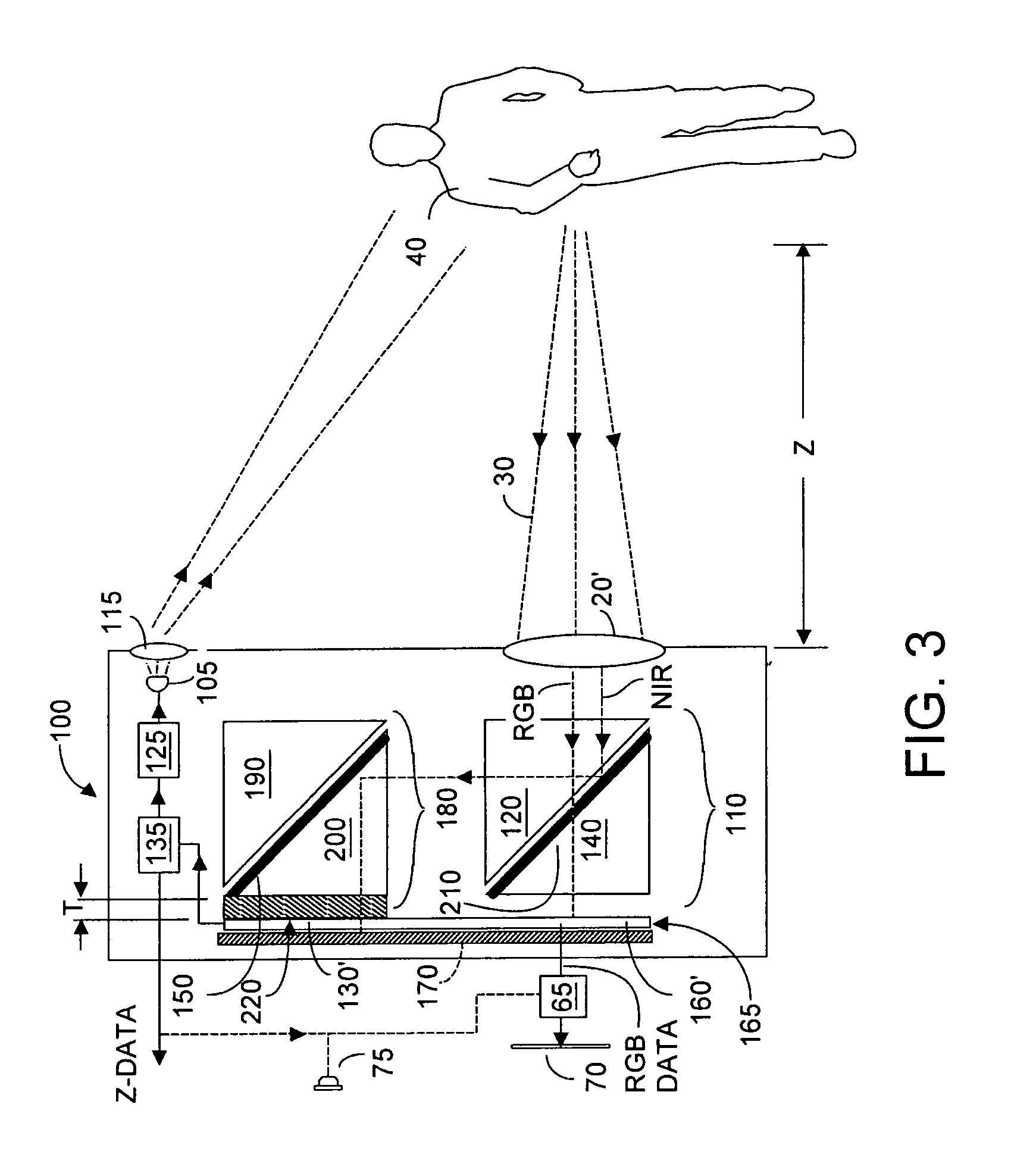
[0026]FIG. 2 depicts a camera system 100 that includes a preferably RGB-Z sensor 110, according to the present invention. As will now be described, RGB-Z sensor 110 includes an array 160 of high resolution pixel detectors responsive to wavelengths in a first spectral band, preferably RGB wavelengths, and an array 130 of lower resolution pixel Z detectors responsive to wavelengths in a second spectral band. The second spectral band may or may not overlap with the...


PUM


Abstract

An RGB-Z sensor is implementable on a single IC chip. A beam splitter such as a hot mirror receives and separates incoming first and second spectral band optical energy from a target object into preferably RGB image components and preferably NIR Z components. The RGB image and Z components are detected by respective RGB and NIR pixel detector array regions, which output respective image data and Z data. The pixel size and array resolutions of these regions need not be equal, and both array regions may be formed on a common IC chip. A display using the image data can be augmented with Z data to help recognize a target object. The resultant structure combines optical efficiency of beam splitting with the simplicity of a single IC chip implementation. A method of using the single chip red, green, blue, distance (RGB-Z) sensor is also disclosed.

Description

CROSS-REFERENCES TO RELATED APPLICATIONS[0001]This application claims priority to U.S. Provisional Patent Application No. 60 / 540,523 filed Jan. 28, 2004 and entitled Single Chip RGBZ Sensor, the entire contents of which is incorporated herein by this reference.BACKGROUND OF THE INVENTION[0002]1. Field of the Invention[0003]The invention relates generally to solid state sensors, and more specifically to such sensors that can be implemented on a single integrated circuit chip, and respond to luminosity information in a first spectral band such as red, green, blue optical wavelengths (which shall be understood to include black and white) to acquire an red-green-blue (RGB) image, and respond to wavelengths in a second spectral band, preferably near-infrared (NIR), to acquire Z data.[0004]2. Description of Related Art[0005]Luminosity-based sensors are known in the art. Such sensors are commonly implemented using CMOS techniques and include an array of pixel detectors responsive to wavele...

Claims


Application Information

Patent Timeline
Patent Type & Authority Patents(United States)
IPC IPC(8): G03B13/00H04N9/07H04N13/02G01C3/08H04N5/225G01J3/28G01J3/36G01S7/481G01S7/4863G01S7/4912G01S17/86G01S17/894G01S17/931H04N9/04H04N9/083
CPCG01C3/08G01J3/2803G01J3/36G01S7/4811G01S7/4863H04N5/2226G01S7/4912G01S17/86G01S17/931G01S17/894H04N23/54H04N23/11H04N9/03
Inventor BAMJI, CYRUSZHAO, PEIQIAN
Owner MICROSOFT TECH LICENSING LLC
Why Eureka
Try Eureka