Duckbill type check valve with curved and resiliently biased closing seal

a resilient bias and check valve technology, applied in the field of duckbill valves and check valves, can solve the problems of insufficient back pressure on the valves to fully close the valve, loose seals, and ineffective seals over time,

Active Publication Date: 2012-03-27
DOIG IAN
View PDF11 Cites 7 Cited by
  • Summary
  • Abstract
  • Description
  • Claims
  • Application Information

AI Technical Summary

Benefits of technology

[0021]In these applications the inlet valves are positioned above the pump and outlet valves to avoid accumulation of solids in the valve housings and the diaphragm pump.

Problems solved by technology

If these valves are the inlet and outlet valves of a reciprocating pump that relies on creating a sub-atmospheric (vacuum) pressure in its inlet line to “lift” water into its inlet when pumping starts, back pressure on the valves can be insufficient to fully close the valve and produce an adequate seal, because the initially flat sealing surfaces tend, with time, to remain partly open.
In the absence of an adequate back pressure, it can be difficult to sustain the seal when the valve is closed.
Stiffening of the tube walls near to the outlet, or closure of a part, or parts, of the outlet provide prior art remedies, but these means introduce disadvantages where the valve is to seal adequately while accommodating slurries containing large solids.
Prior art invention WO 2006 / 108219 provides means of reinforcing the duck beak to operate against a higher outlet pressure, but does not ameliorate the problem of decay causing the seal to become loose and ineffective over time.

Method used


Image

  • Duckbill type check valve with curved and resiliently biased closing seal
  • Duckbill type check valve with curved and resiliently biased closing seal
  • Duckbill type check valve with curved and resiliently biased closing seal

Examples


Embodiment Construction

[0031]Preferred embodiments of the invention will now be described, by way of examples only, with reference to the accompanying drawings in which:

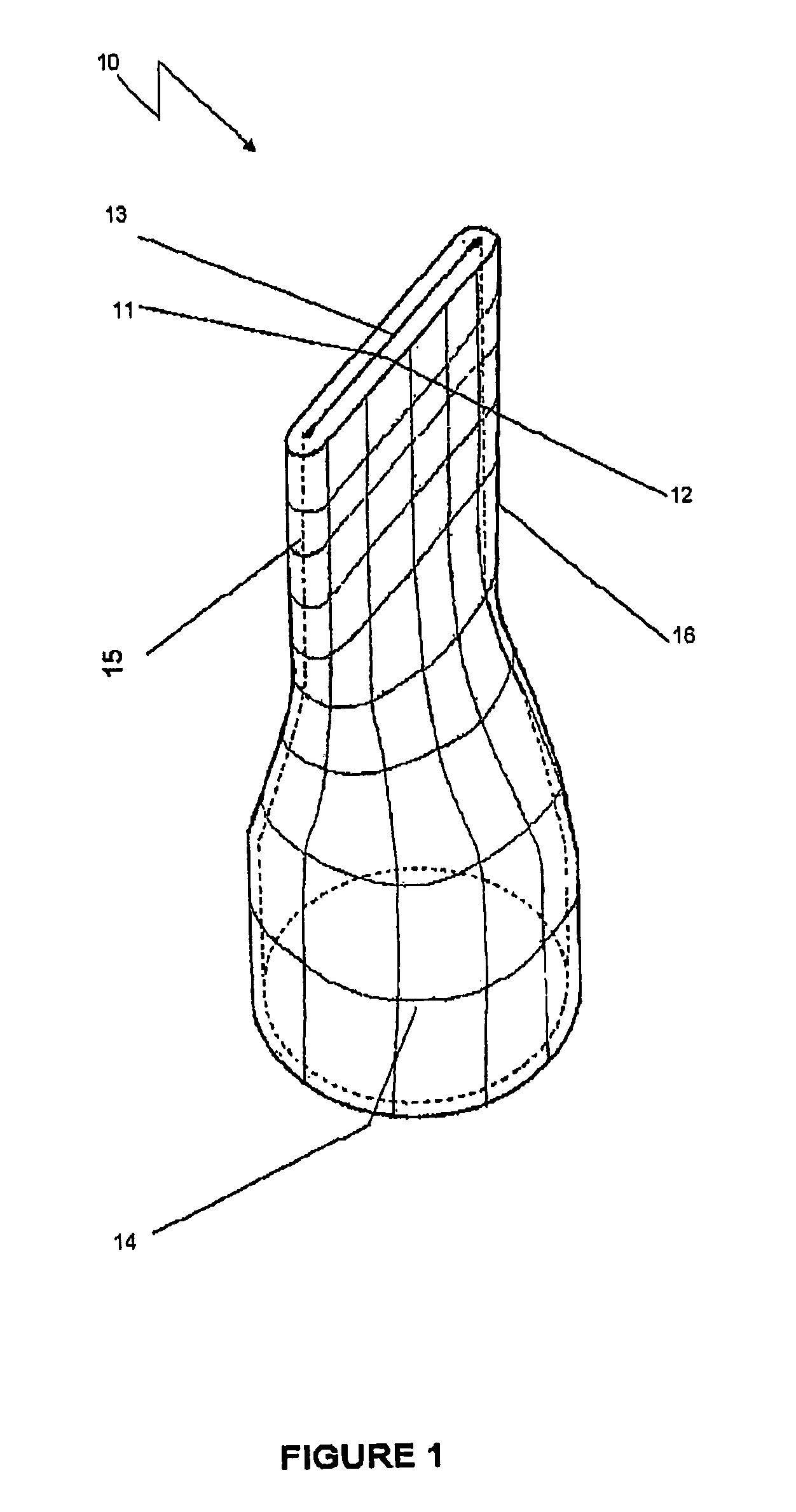
[0032]FIG. 1 shows a view of the flexible parts of a closed duck beak check valve 10 with an outlet 13 and an inlet 14. It has the form of a tube flattened towards its outlet end. First and second inner surfaces 11 and 12 are flat and meet to form the valve seal. Each side 15 and 16 of the flattened tube is rounded and biased to sustain the flattened shape in its relaxed state as shown.

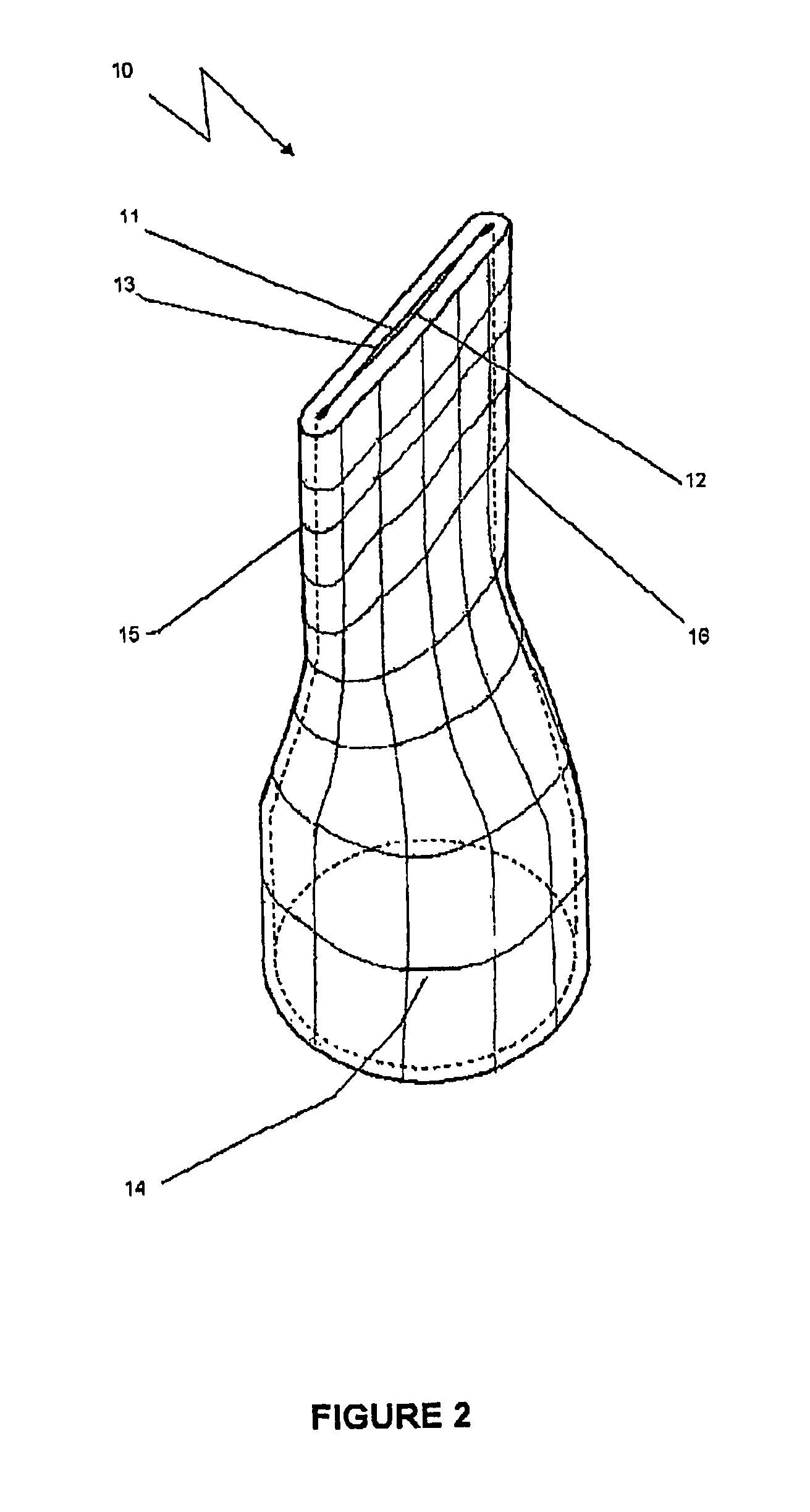
[0033]FIG. 2 shows the duck-beak check valve of FIG. 1 with the inner surfaces 11 and 12 slightly separated at the outlet. FIG. 2 illustrates what happens after a period in service when the downstream (or back) pressure on the valve is inadequate to fully close the valve. Like numerals indicate features in common with FIG. 1.

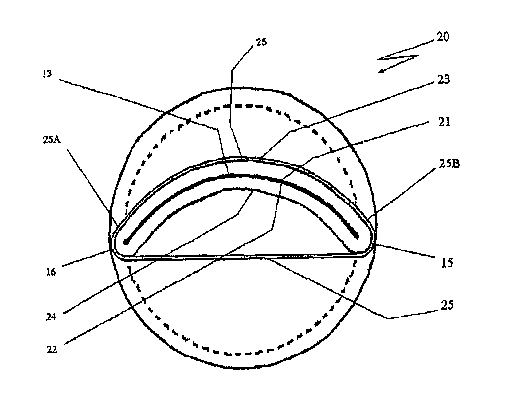
[0034]FIG. 3 shows an end view of a duck beak check valve 20 in accordance with an embodiment of the invention in which like numerals i...


PUM


Abstract

A check valve is provided comprising a conduit for conveying a fluid, the conduit having an inlet and an outlet, the conduit having a first region adjacent the outlet (13) comprising a flexible wall, two opposing sides of the flexible wall converging towards each other to form a closed geometry when the pressure of the fluid upstream of the inlet and the pressure of the fluid downstream of the outlet are substantially equal, the closed geometry comprising each of the opposing sides (23, 24) being arcuate in cross-section and lying against each other in a substantially sealing relationship (21, 22). Preferably, two connecting regions of the wall connecting the two opposing sides (15, 16) are biased towards each other by a biasing means. Preferably, the biasing means comprises one or more flexible ring members (25) encircling the flexible wall attached at points (25A and 25B). Preferably, the conduit takes the form of a duck beak valve (20). The figure shows an end view onto the check valve outlet.

Description

[0001]This application is a U.S. National Stage application of PCT Application No. PCT / AU2008 / 000619, with an international filing date of May 5, 2008, and claims priority based on Australian application 2007902382, filed May 7, 2007, which is incorporated herein by reference.FIELD OF THE INVENTION[0002]The present invention relates to check valves and duck-beak valves.BACKGROUND OF THE INVENTION[0003]Duck beak check valves typically have a tubular inlet part that flattens towards its outlet—like the beak of a duck. In some duck beak valves the downstream parts are split at each side to form two opposing flaps.[0004]Duck beak valves are used to control the influx of tidal waters into sewer and storm water outlets that discharge waste-water into open waters. They were also used as the check valve on World War II gas masks.[0005]Current “duck beak” check valves rely on a superior downstream (“back”) pressure to close sealingly. If these valves are the inlet and outlet valves of a reci...

Claims


Application Information

Patent Timeline
Patent Type & Authority Patents(United States)
IPC IPC(8): F16K15/14
CPCF16K15/147Y10T137/3331Y10T137/7882Y10T137/7883
Inventor DOIG, IAN
Owner DOIG IAN
Why Eureka
Try Eureka