Spring collars having permanent magnets for non-use storage

a technology of spring collars and magnets, which is applied in the field of spring collars, can solve the problems of reducing the likelihood of future use of spring collars and potent tripping hazards, and achieve the effect of increasing the diameter of the central apertur

Inactive Publication Date: 2012-03-27
EMBERSTONE TECH
View PDF21 Cites 25 Cited by
  • Summary
  • Abstract
  • Description
  • Claims
  • Application Information

AI Technical Summary

Benefits of technology

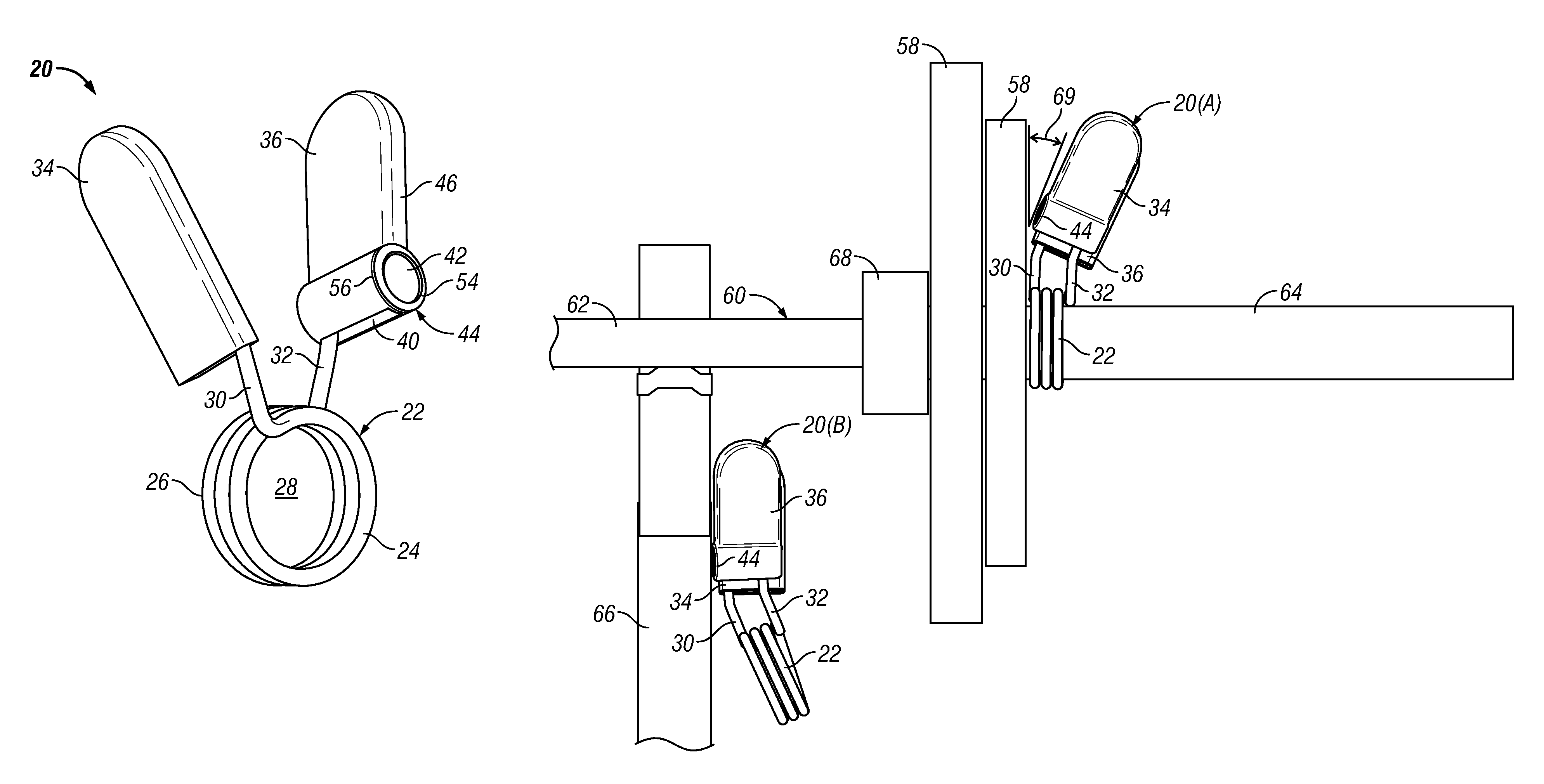
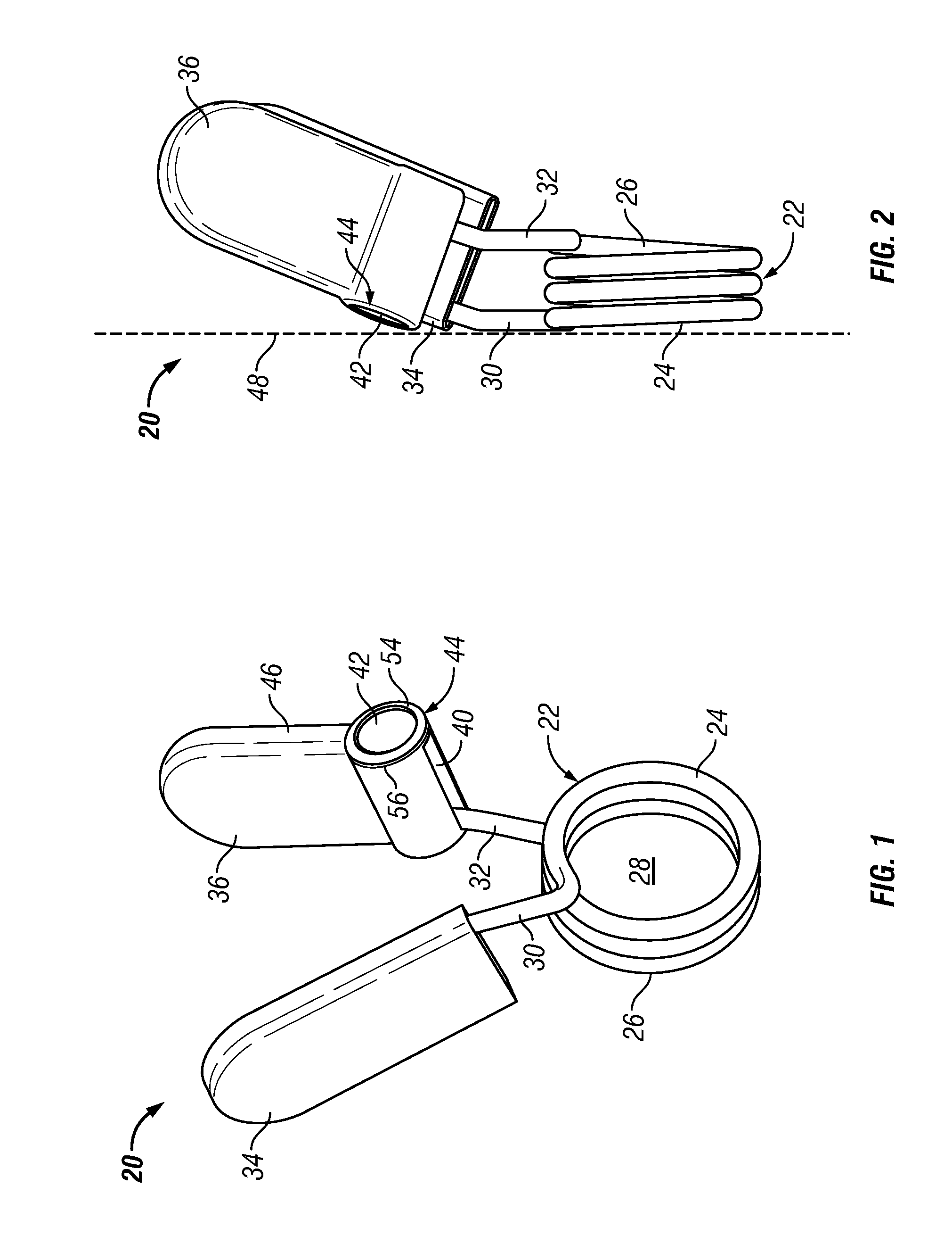
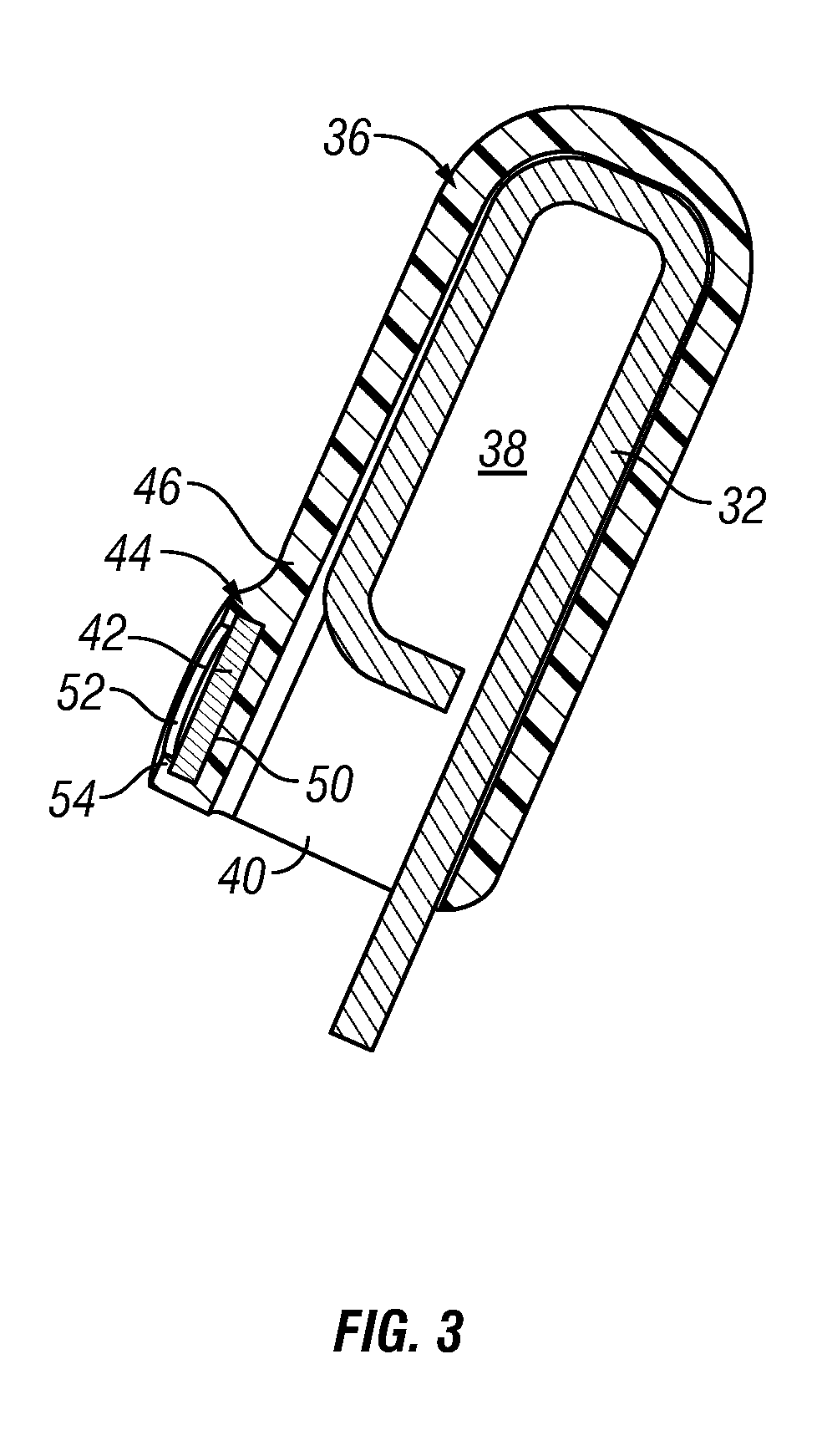
[0007]To satisfy one or more of the foregoing objectives, embodiments of a spring collar are provided for removably securing a disc weight to the sleeve of a barbell. In one embodiment, the spring collar includes a resilient wire form having a permanent magnet mounted thereto. The resilient wire form includes a coiled body having a central aperture, and first and second radial arms extending from the coiled body. The first and second radial arms can be moved toward one another to increase the diameter of the central aperture and permit a user to slide the coiled body over the sleeve. The permanent magnet enables a user to removably secure the spring collar to a ferromagnetic surface when the spring collar is not in use.

Problems solved by technology

However, rarely is there provided a convenient place or manner in which to store a pair of spring collars on or near a piece of exercise equipment when the exercise equipment is not in use.
As a result, spring collars are frequently placed on the gym floor where the spring collars may be inadvertently moved, may be damaged, and pose a potential tripping hazard.
Furthermore, when placed on the gym floor, a set of spring collars is not prominently visually displayed near each piece of exercise equipment, which decreases the likelihood of future use of the spring collars.

Method used


Image

  • Spring collars having permanent magnets for non-use storage
  • Spring collars having permanent magnets for non-use storage
  • Spring collars having permanent magnets for non-use storage

Examples


Embodiment Construction

[0017]The following Detailed Description is merely exemplary in nature and is not intended to limit the invention or the application and uses of the invention. Furthermore, there is no intention to be bound by any theory presented in the preceding Background or the following Detailed Description. As appearing herein, the phrase “permanent magnet” is defined to include any structural element or assemblage of structural elements that retains a magnetic field in the absence of an inducing field or current, including composite magnets, rare earth magnets, polymer-bonded magnets, and magnetic assemblies. The phrase “ferromagnetic surface” is defined herein to include any surface or body to which a permanent magnet is attracted including, but not limited to, steel beams and other structural members of the type commonly utilized in the manufacture of exercise equipment.

[0018]FIGS. 1 and 2 are isometric and side views, respectively, of a spring collar 20 in a non-deflected state in accordan...


PUM


Abstract

To satisfy one or more of the foregoing objectives, embodiments of a spring collar are provided for removably securing a disc weight to the sleeve of a barbell. In one embodiment, the spring collar includes a resilient wire form having a permanent magnet mounted thereto. The spring collar includes a coiled body having a central aperture, and first and second radial arms extending from the coiled body. The first and second radial arms can be moved toward one another to increase the diameter of the central aperture and permit a user to slide the coiled body over the sleeve. The permanent magnet enables a user to removably secure the spring collar to a ferromagnetic surface when the spring collar is not in use.

Description

CROSS-REFERENCES TO RELATED APPLICATIONS[0001]This Application claims priority to U.S. Provisional Application Ser. No. 61 / 164,873, filed Mar. 30, 2009, the contents of which are hereby incorporated by reference.TECHNICAL FIELD[0002]The present invention relates generally to exercise equipment and, more particularly, to embodiments of a spring collar including at least one permanent magnet enabling a user to removably secure the spring collar to a ferromagnetic surface when the spring collar is not in use.BACKGROUND[0003]An adjustable-weight barbell is an exercise bar onto which a number of modular disc weights (commonly referred to as “plates”) can be removably loaded by a user. Several forms of adjustable-weight barbells are known and commercially available. One well-known barbell (commonly referred to as an “Olympic bar”) assumes the form of a straight bar approximately 5-7 feet in length that is often utilized to perform bench press, military press, squat, and dead lift exercise...

Claims


Application Information

Patent Timeline
Patent Type & Authority Patents(United States)
IPC IPC(8): A63B21/075A63B23/16A63B71/00
CPCA63B21/0728A63B71/0036A63B2209/08
Inventor LEACH, JUSTIN JAMESFULLER, CHAD GORDONKAZOR, EDWARDSIDENER, PATRICK AARON
Owner EMBERSTONE TECH
Why Eureka
Try Eureka