Audio gain control using specific-loudness-based auditory event detection

a gain control and specific loudness technology, applied in the field of audio dynamic range control methods and apparatuses, can solve the problems of introducing unwanted perceptible changes in the audio, introducing audible artifacts in the conventional audio dynamics process, and unable to assess the gain control (agc) and dynamic range compression (drc) , to achieve the effect of reducing audible artifacts

Active Publication Date: 2012-03-27
DOLBY LAB LICENSING CORP
View PDF156 Cites 88 Cited by
  • Summary
  • Abstract
  • Description
  • Claims
  • Application Information

AI Technical Summary

Benefits of technology

[0012]Auditory scene analysis identifies perceptually discrete auditory events, with each event occurring between two consecutive auditory event boundaries. The audible impairments caused by a gain change can be greatly reduced by ensuring that within an auditory event the gain is more nearly constant and by confining much of the change to the neighborhood of an event boundary. In the context of compressors or expanders, the response to an increase in audio level (often called the attack) may be rapid, comparable with or shorter than the minimum duration of auditory events, but the response to a decrease (the release or recovery) may be slower so that sounds that ought to appear constant or to decay gradually may be audibly disturbed. Under such circumstances, it is very beneficial to delay the gain recovery until the next boundary or to slow down the rate of change of gain during an event. For automatic gain control applications, where the medium- to long-term level or loudness of the audio is normalized and both attack and release times may therefore be long compared with the minimum duration of an auditory event, it is beneficial during events to delay changes or slow down rates of change in gain until the next event boundary for both increasing and decreasing gains.
[0015]By controlling key audio dynamics processing parameters using the results of auditory scene analysis, a dramatic reduction of audible artifacts introduced by dynamics processing may be achieved.

Problems solved by technology

Prior art methods such as automatic gain control (AGC) and dynamic range compression (DRC) do not assess in any psychoacoustically-based way the time intervals during which gain changes may be perceived as impairments and when they can be applied without imparting audible artifacts.
Therefore, conventional audio dynamics processes can often introduce audible artifacts, i.e., the effects of the dynamics processing can introduce unwanted perceptible changes in the audio.

Method used


Image

  • Audio gain control using specific-loudness-based auditory event detection
  • Audio gain control using specific-loudness-based auditory event detection
  • Audio gain control using specific-loudness-based auditory event detection

Examples


Embodiment Construction

Auditory Scene Analysis

Original, Non-Loudness Domain Method

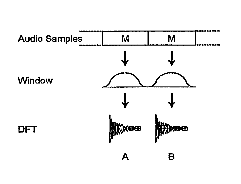
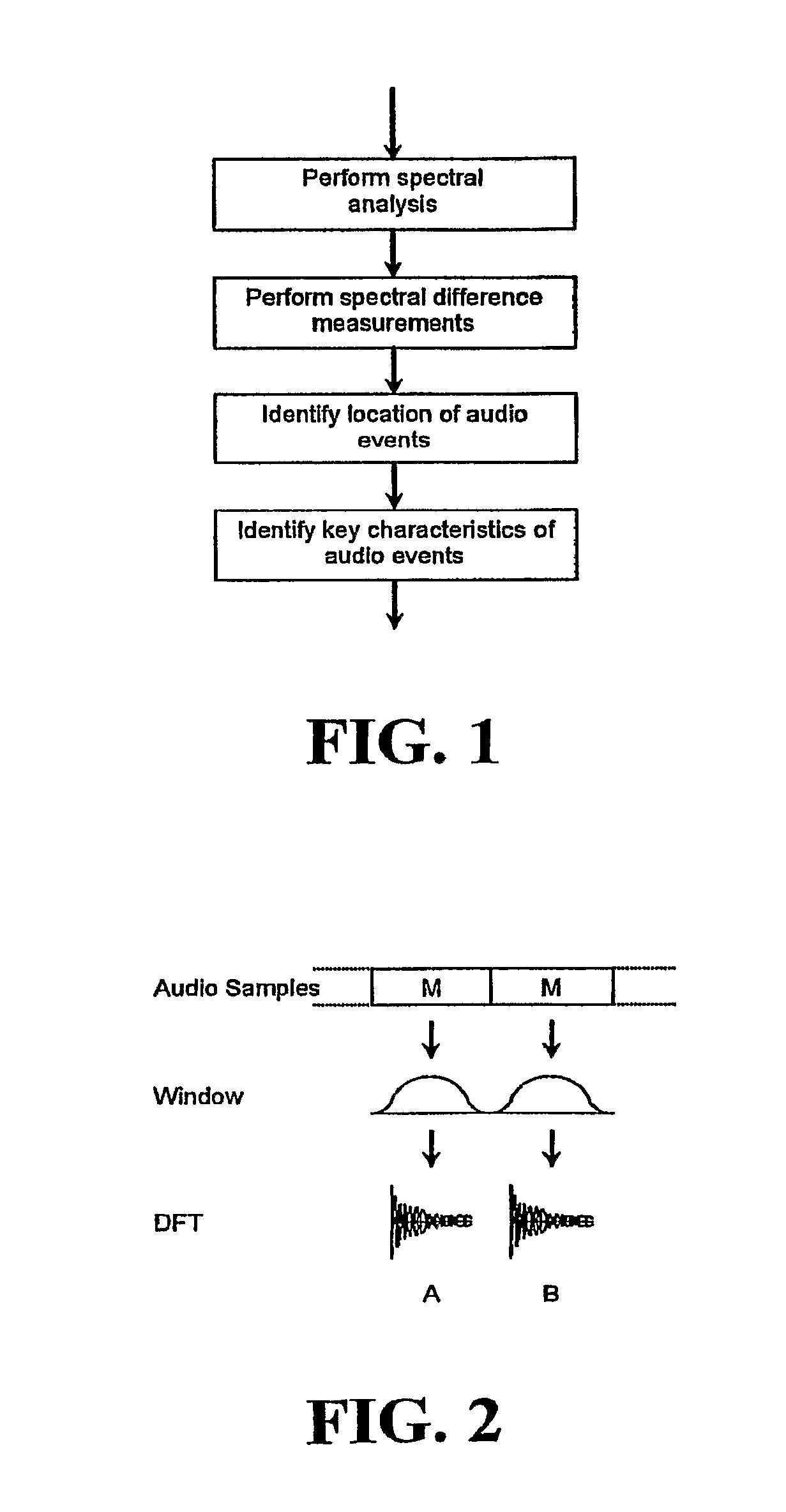
[0029]In accordance with an embodiment of one aspect of the present invention, auditory scene analysis may be composed of four general processing steps as shown in a portion of FIG. 1. The first step 1-1 (“Perform Spectral Analysis”) takes a time-domain audio signal, divides it into blocks and calculates a spectral profile or spectral content for each of the blocks. Spectral analysis transforms the audio signal into the short-term frequency domain. This may be performed using any filterbank, either based on transforms or banks of bandpass filters, and in either linear or warped frequency space (such as the Bark scale or critical band, which better approximate the characteristics of the human ear). With any filterbank there exists a tradeoff between time and frequency. Greater time resolution, and hence shorter time intervals, leads to lower frequency resolution. Greater frequency resolution, and hence narrower subbands, lead...


PUM


Abstract

In one disclosed aspect, dynamic gain modifications are applied to an audio signal at least partly in response to auditory events and / or the degree of change in signal characteristics associated with said auditory event boundaries. In another aspect, an audio signal is divided into auditory events by comparing the difference in specific loudness between successive time blocks of the audio signal.

Description

TECHNICAL FIELD[0001]The present invention relates to audio dynamic range control methods and apparatus in which an audio processing device analyzes an audio signal and changes the level, gain or dynamic range of the audio, and all or some of the parameters of the audio gain and dynamics processing are generated as a function of auditory events. The invention also relates to computer programs for practicing such methods or controlling such apparatus.[0002]The present invention also relates to methods and apparatus using a specific-loudness-based detection of auditory events. The invention also relates to computer programs for practicing such methods or controlling such apparatus.BACKGROUND ARTDynamics Processing of Audio[0003]The techniques of automatic gain control (AGC) and dynamic range control (DRC) are well known and are a common element of many audio signal paths. In an abstract sense, both techniques measure the level of an audio signal in some manner and then gain-modify the...

Claims


Application Information

Patent Timeline
Patent Type & Authority Patents(United States)
IPC IPC(8): H04R29/00H03G5/00G10L21/034G10L21/0364
CPCH03G1/00H03G3/3089H03G7/007H03G9/005H03G3/30H03G7/00G10L25/51H04R3/00H03G3/3005H04R3/04H04R2430/03G10L21/038G10L25/21
Inventor CROCKETT, BRETT GRAHAMSEEFELDT, ALAN JEFFREY
Owner DOLBY LAB LICENSING CORP
Why Eureka
Try Eureka