Covering structure of a mixer

a technology of mixer and cover, applied in the field of mixer structure, can solve the problems of mixer producing vibration, dangerous for consumers, complicated and time-consuming, etc., and achieve the effects of convenient cleaning for users, simple structure, and quick assembly and disassembly

Active Publication Date: 2012-04-03
SPAR FOOD MACHINERY MFG
View PDF13 Cites 6 Cited by
  • Summary
  • Abstract
  • Description
  • Claims
  • Application Information

AI Technical Summary

Benefits of technology

[0008]An objective of the invention is to provide a covering structure of a mixer that has a simple structure to be quickly assembled and disassembled. This is convenient for the user to clean.

Problems solved by technology

This is very complicated and time-consuming.
Moreover, the mixer produces vibrations.
This is very dangerous for consumers.
However, after the connecting ring 7 is uninstalled, the rotating ring 5 is likely to be rotated and trigger the safety ring by mistake, resulting in the self-operation of the head of the mixer.

Method used


Image

  • Covering structure of a mixer
  • Covering structure of a mixer
  • Covering structure of a mixer

Examples


Embodiment Construction

[0030]The present invention will be apparent from the following detailed description, which proceeds with reference to the accompanying drawings, wherein the same references relate to the same elements.

[0031]First, please refer to FIGS. 1 and 2. This embodiment of the invention is used only for the purpose of illustration. The invention is not restricted by this example.

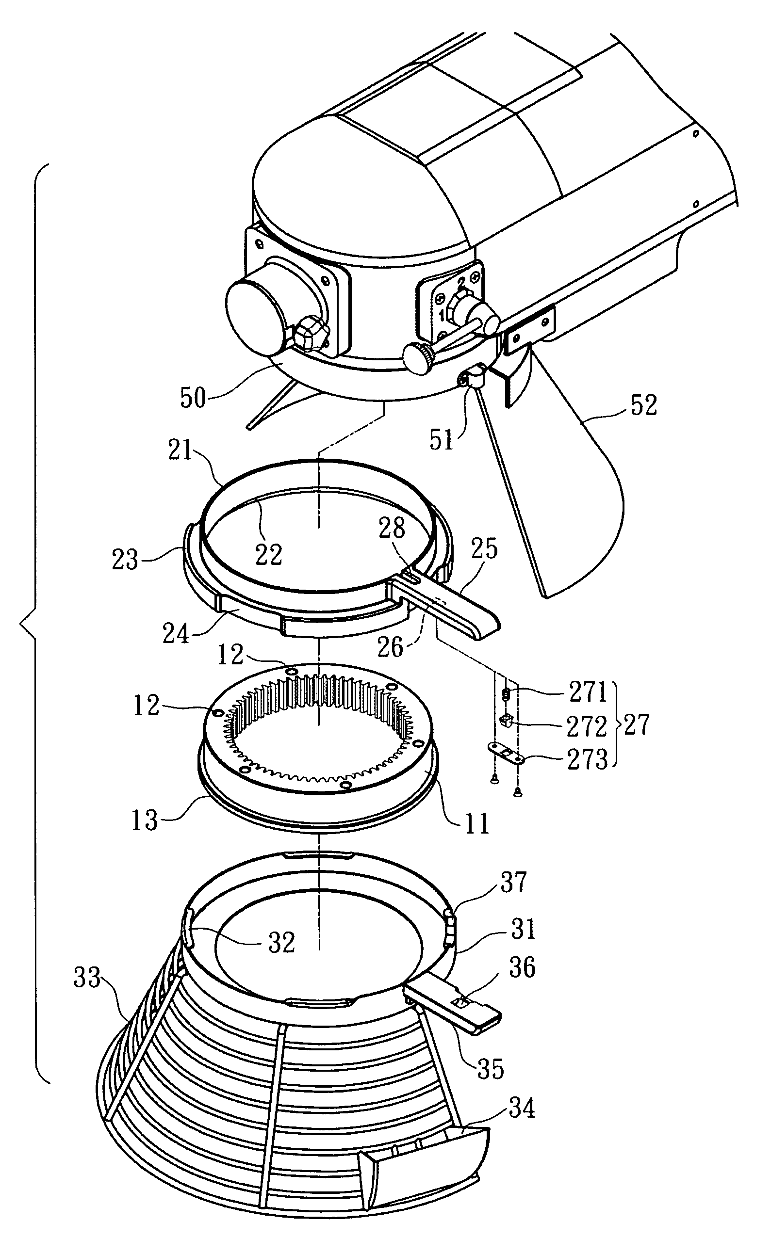
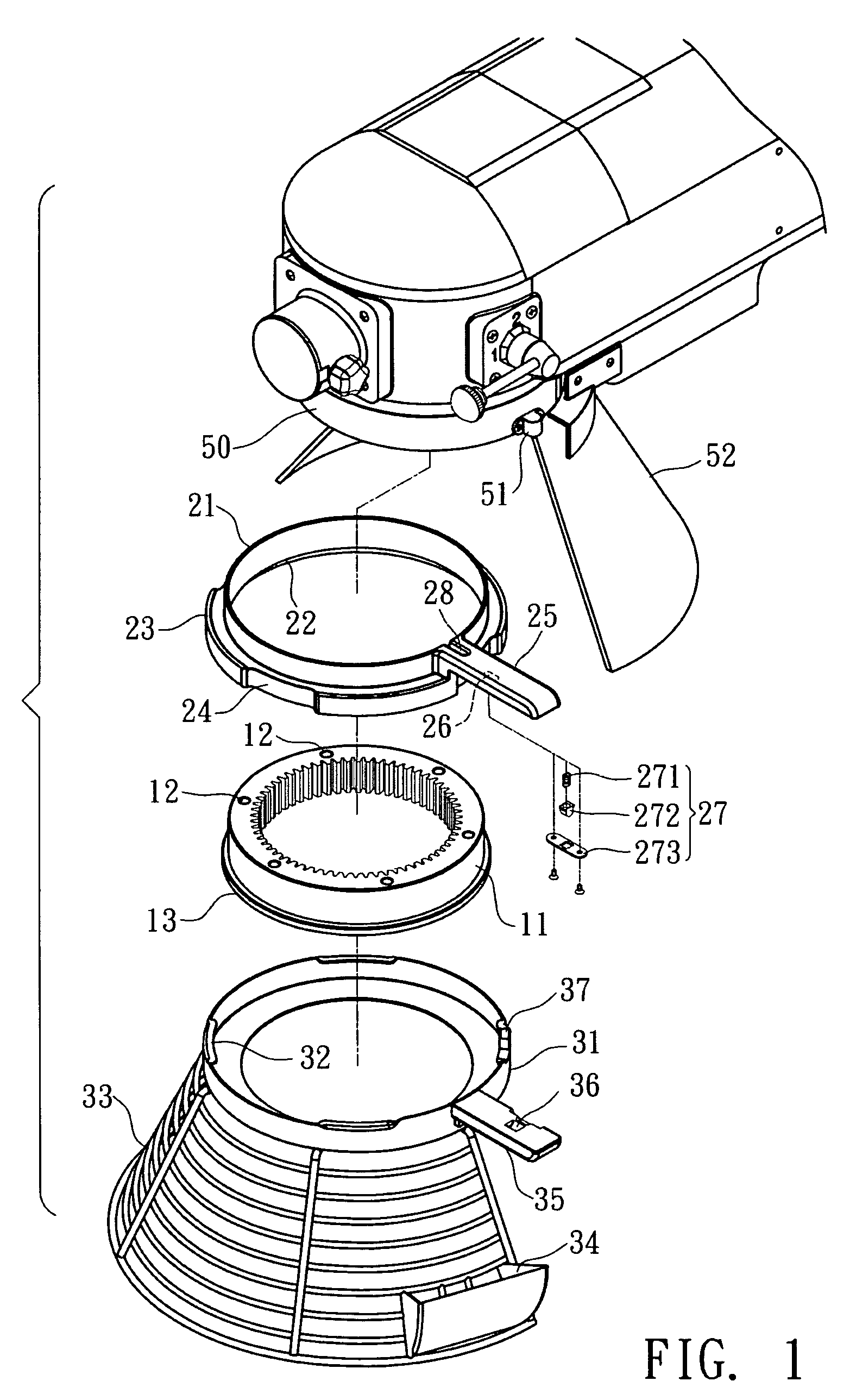
[0032]The disclosed covering structure of a mixer includes a fixed ring 11, an upper ring 21, and a lower ring 31.

[0033]The fixed ring 11 has several through holes 12 formed at equal interval on its ring surface. A protruding ring 13 surrounds the outer wall of the fixed ring 11. A screw (not shown) goes through each of the through holes 12 from bottom to top, so that the fixed ring 11 can be fixed to the bottom surface of the head 50 of a mixer. One side of the head 50 is provided with a restricting assembly 51 that performs a vertical reciprocal motion. The peripheral of the head 50 is connected with a half umbrell...


PUM


Abstract

A covering structure of a mixer includes: a fixed ring connected to the head of a mixer; an upper ring; and a lower ring. The fixed ring is further surrounded by a protruding ring. The upper ring has a striding part on its inner wall to stride on the protruding ring. The upper ring further has at least two stopping parts at an interval. A concave part is formed between each pair of consecutive stopping parts. One end of the lower ring is formed with connecting parts whose number is the same as that of the stopping parts. Its other end is connected downward with a covering element. The connecting parts of the lower ring are inserted via the concave parts on the upper ring and above them. By rotating the lower ring, the connecting parts urge against the stopping parts to form a rotating ring that can rotate along the protruding ring.

Description

BACKGROUND OF THE INVENTION[0001]1. Field of Invention[0002]The invention relates to a mixer structure and, in particular, to a covering structure of a mixer.[0003]2. Related Art[0004]As shown in FIG. 11, the conventional covering structure of a mixer has a fixed ring 2 fixed around the stirring bar at the bottom surface of the head 1 of the mixer. The lower section of the outer ring surface of the fixed ring 2 is extended with a protruding edge 3. A striding ring 6 protrudes from the top edge of the inner ring surface of a rotating ring 5. The rotating ring 5 is mounted on the upper surface of the protruding edge 3 using the lower surface of its striding ring 6. The bottom surface of the rotating ring 5 is fixed with a connecting ring 7. The lower part of the connecting ring 7 is further soldered with a protecting mesh 8. A protecting cover 9 is connected to the neck part of the mixer using its back. When the operator pushes or drags the protecting mesh 8 sideways, the rotating rin...

Claims


Application Information

Patent Timeline
Patent Type & Authority Patents(United States)
IPC IPC(8): B01F15/00
CPCB01F7/1605B01F13/04B01F13/045F16P1/02B01F27/805B01F35/60B01F35/605
Inventor HUANG, KUN-CHUNG
Owner SPAR FOOD MACHINERY MFG
Why Eureka
Try Eureka