Header connector assembly

a header connector and connector technology, applied in the direction of couplings/cases, coupling device connections, substation/switching arrangement details, etc., can solve the problem of transmission fluid in the transmission case leaking out of the transmission cas

Active Publication Date: 2012-04-03
TYCO ELECTRONICS LOGISTICS AG (CH)
View PDF21 Cites 43 Cited by
  • Summary
  • Abstract
  • Description
  • Claims
  • Application Information

AI Technical Summary

Benefits of technology

[0006]In one embodiment, a header connector assembly is provided. The header connector assembly includes an outer housing, an inner housing, a shield subassembly, and a seal body. The outer housing is disposed in an opening of a panel and includes a cavity. The inner housing includes a channel and is disposed in the opening of the panel. The inner housing is received in the cavity of the outer housing and includes a channel configured to have a contact disposed therein. The shield subassembly is disposed between the outer housing and the inner housing. The shield subassembly engages the panel to electrically couple the shield subassembly with the panel. The seal body is disposed between the panel and at least one of the outer housing and the inner housing. The seal body restricts passage of contaminants between the panel and at least one of the outer housing and the inner housing.
[0008]In another embodiment, another header connector assembly is provided. The header connector assembly includes a housing subassembly, a contact, an outer conductive shield, an inner conductive shield, and a seal body. The housing subassembly is disposed in an opening of a panel and includes a channel. The contact is disposed in the channel of the housing subassembly and is configured to engage a conductive member of a connector that mates with the housing subassembly. The outer conductive shield is joined to the housing subassembly and engages the panel along a perimeter of the housing subassembly. The outer conductive shield includes an opening extending therethrough. The inner conductive shield extends through the opening in the outer conductive shield and is electrically coupled with the outer conductive shield. The inner conductive shield defines an interior chamber with the channel of the housing subassembly disposed therein. The seal body is disposed between the panel and the housing subassembly. The seal body restricts passage of contaminants between the panel and the housing subassembly.

Problems solved by technology

Contaminants that ingress into the connector may short out or otherwise interfere with transfer of the high voltage current through the connector, or may result in transmission fluid in the transmission case leaking out of the transmission case.

Method used


Image

  • Header connector assembly
  • Header connector assembly
  • Header connector assembly

Examples


Embodiment Construction

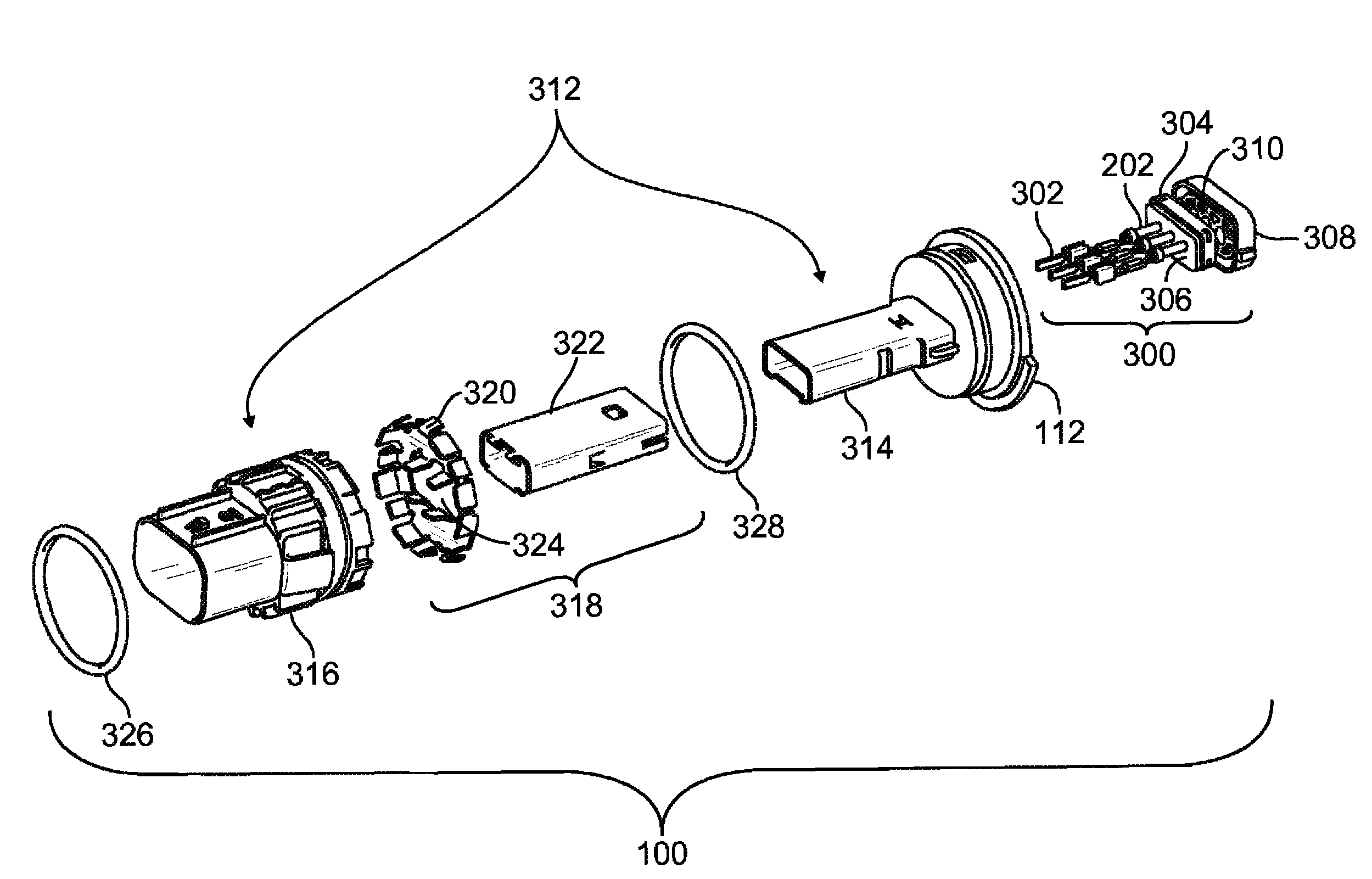
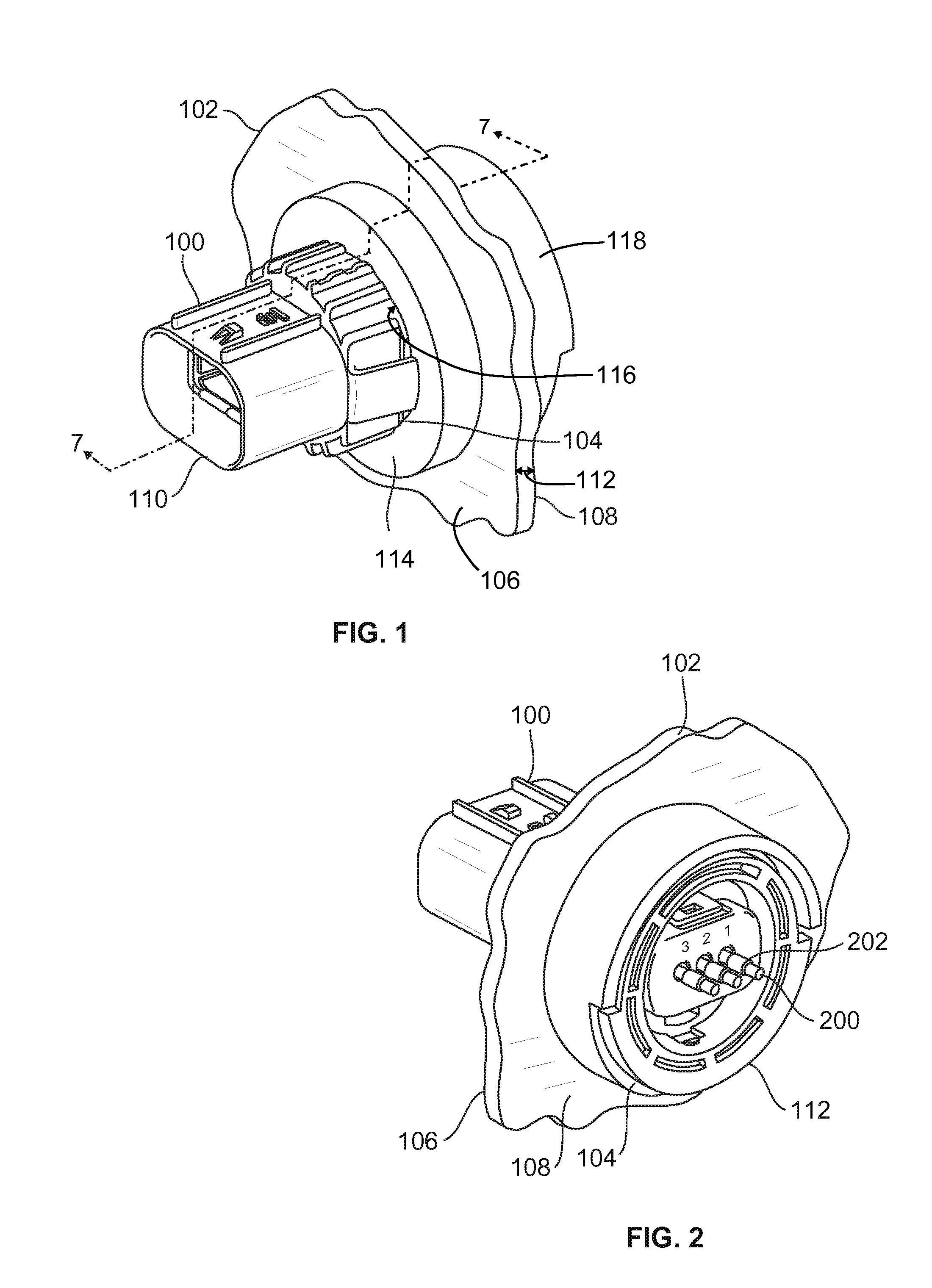
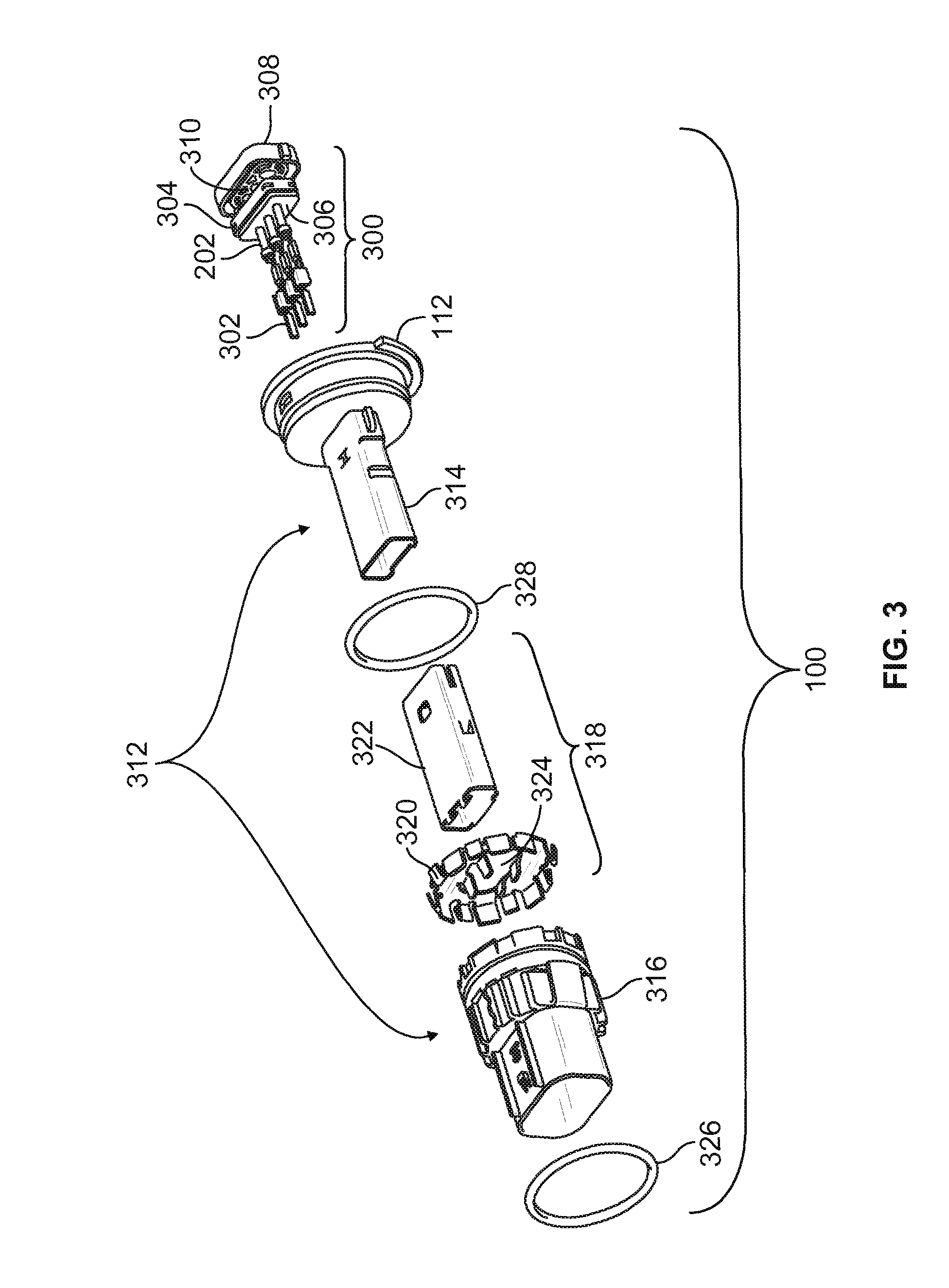
[0017]FIG. 1 is a perspective view of a header connector assembly 100 mounted in a panel 102 in accordance with one embodiment of the present disclosure. FIG. 2 is another perspective view of the header connector assembly 100. The header connector assembly 100 is mounted to the panel 102 by placing the header connector assembly 100 through an opening 104 in the panel 102. FIG. 1 shows the header connector assembly 100 from a front side 106 of the panel 102 while FIG. 2 shows the header connector assembly 100 from a back side 108 of the panel 102. The header connector assembly 100 extends to a mating end 110 that protrudes from the front side 106 of the panel 102 and to a back end 112 that protrudes from or is disposed near the back side 108 of the panel 102 in the illustrated embodiment.

[0018]The header connector assembly 100 mates with a connector 800 (shown in FIG. 8) at the mating end 110 from the front side 106 of the panel 102. Contacts 302 (shown in FIG. 3) in the header conne...


PUM


Abstract

A header connector assembly includes an outer housing, an inner housing, a shield subassembly, and a seal body. The outer housing is disposed in an opening of a panel and includes a cavity. The inner housing includes a channel and is disposed in the opening of the panel. The inner housing is received in the cavity of the outer housing and includes a channel configured to have a contact disposed therein. The shield subassembly is disposed between the outer housing and the inner housing. The shield subassembly engages the panel to electrically couple the shield subassembly with the panel. The seal body is disposed between the panel and at least one of the outer housing and the inner housing. The seal body restricts passage of contaminants between the panel and at least one of the outer housing and the inner housing.

Description

BACKGROUND OF THE INVENTION[0001]The subject matter described herein relates generally to electrical connectors, and more particularly, to shielded header connectors.[0002]Transmissions in some automobiles may include a transmission case that has wires extending from the case or a connector joined to the case. The wires may be coupled with other components or the connector may be joined with another connector in the automobile to transfer current to the transmission. The current may be used to shift or change gears in the transmission, or operate a pump of the transmission, for example.[0003]The wires or connectors exit from the transmission case from openings in the case. These openings may need to be sealed in order to prevent contaminants from outside of the transmission case, such as moisture, dirt, and the like, from entering into the transmission case via the openings. Additionally, the openings may need to be sealed to prevent contaminants inside the transmission case, such a...

Claims


Application Information

Patent Timeline
Patent Type & Authority Patents(United States)
IPC IPC(8): H01R13/73
CPCH01R13/65802H01R13/5202H01R13/502H01R13/74H01R13/6584H01R13/52H01R13/658
Inventor RHEIN, DAVID JAMES
Owner TYCO ELECTRONICS LOGISTICS AG (CH)
Why Eureka
Try Eureka