Flowmeter transducer magnetic clamping

a technology of magnetic clamping and flowmeter, which is applied in the direction of instruments, measurement devices, apparel, etc., can solve the problems of reducing the accuracy and reliability of flow sensors, affecting the operation of the transducer, and requiring frequent maintenance, so as to reduce the tangential force, stable acoustic connection, and high mating pressure

Inactive Publication Date: 2012-04-10
ONICON INC
View PDF10 Cites 8 Cited by
  • Summary
  • Abstract
  • Description
  • Claims
  • Application Information

AI Technical Summary

Benefits of technology

[0008]One aspect of the present invention is that it provides a method for substantially reducing tangential forces present at the mating area between a clamp-on transducer and a pipe. In one preferred embodiment this is accomplished by the use of at least one low friction bearing on a portion of a transducer housing distal from the pipe. This arrangement aids in translating the tension in a clamp band to a clamping force directed substantially entirely along a radius of the pipe. Because non-radial forces are reduced, the transducer housing may be made relatively tall to enable high mating pressures to be realized. This can result in a more stable acoustic connection and improved meter performance.

Problems solved by technology

When these bands are tightened during installation, unbalanced frictional forces can move the transducer tangential to the pipe and can torque a portion of the transducer away from intimate acoustic contact with the pipe.
Moreover, clamp band tension can change due to temperature or other factors, thus leading to flow sensor drift and loss of precision and reliability.
Because coupling promoters tend to evaporate, wick away or otherwise degrade or leave the area over a period of time, the transducer mounting may require frequent maintenance effort.
In these cases, the increase in clamp band tension needed for a reliable acoustic connection tends to become excessive, thus dissipating any advantage gained by this procedure.

Method used


Image

  • Flowmeter transducer magnetic clamping
  • Flowmeter transducer magnetic clamping
  • Flowmeter transducer magnetic clamping

Examples


Embodiment Construction

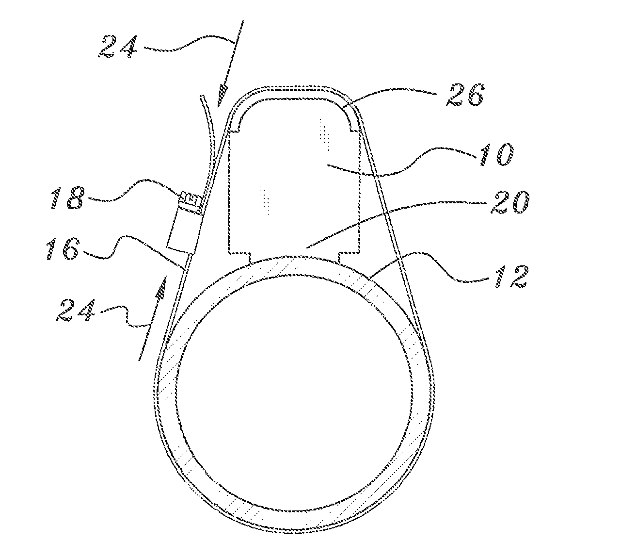
[0019]In studying this Detailed Description, the reader may be aided by noting definitions of certain words and phrases used throughout this patent document. Wherever those definitions are provided, those of ordinary skill in the art should understand that in many, if not most instances, such definitions apply to both preceding and following uses of such defined words and phrases. At the outset of this Description, one may note that the terms “include” and “comprise,” as well as derivatives thereof, mean inclusion without limitation; the term “or,” is inclusive, meaning and / or. Moreover, the term ‘tangential’ refers to a direction, measured at an external surface of a pipe, that is mutually perpendicular to a pipe axis and to any pipe radius.

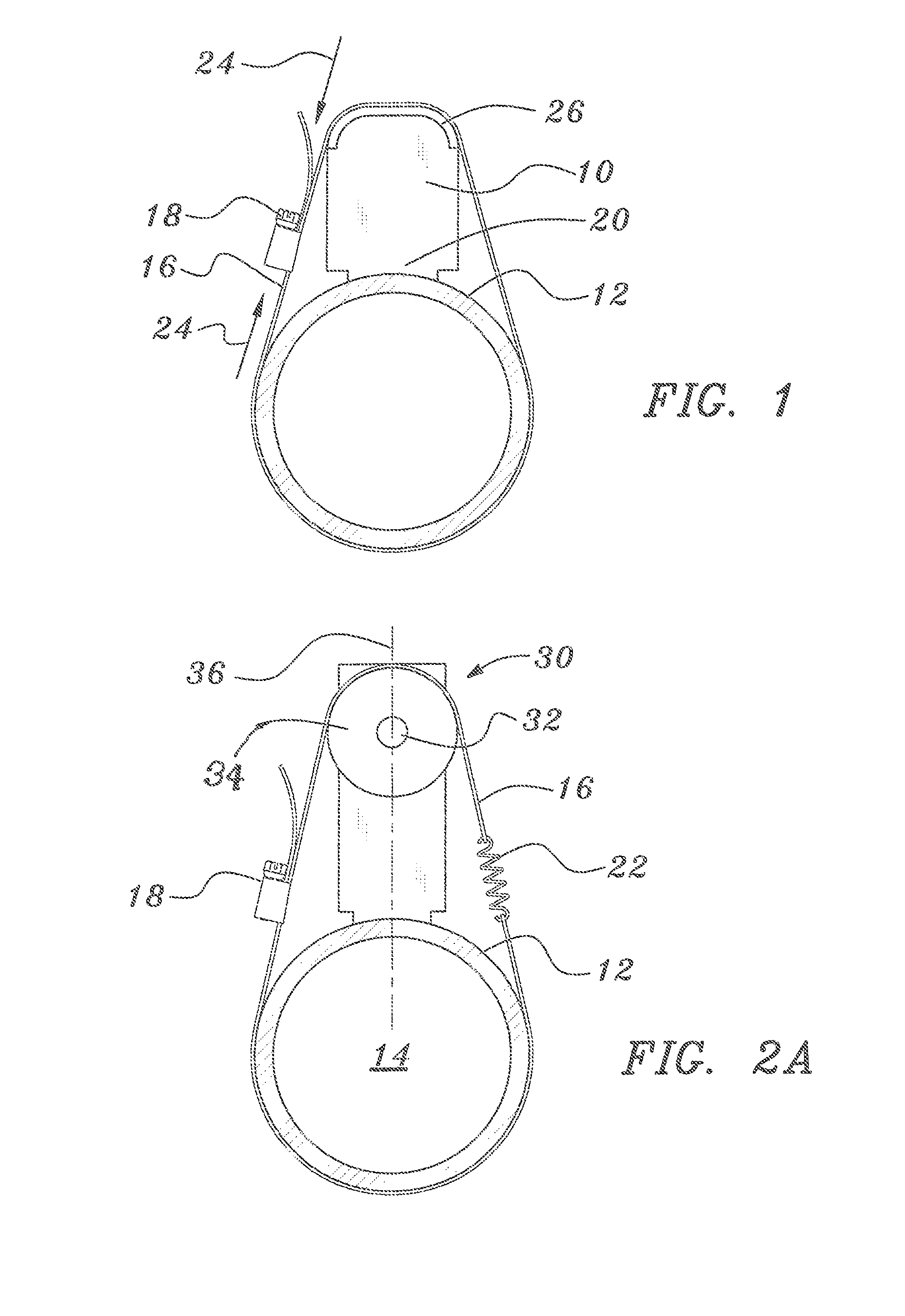
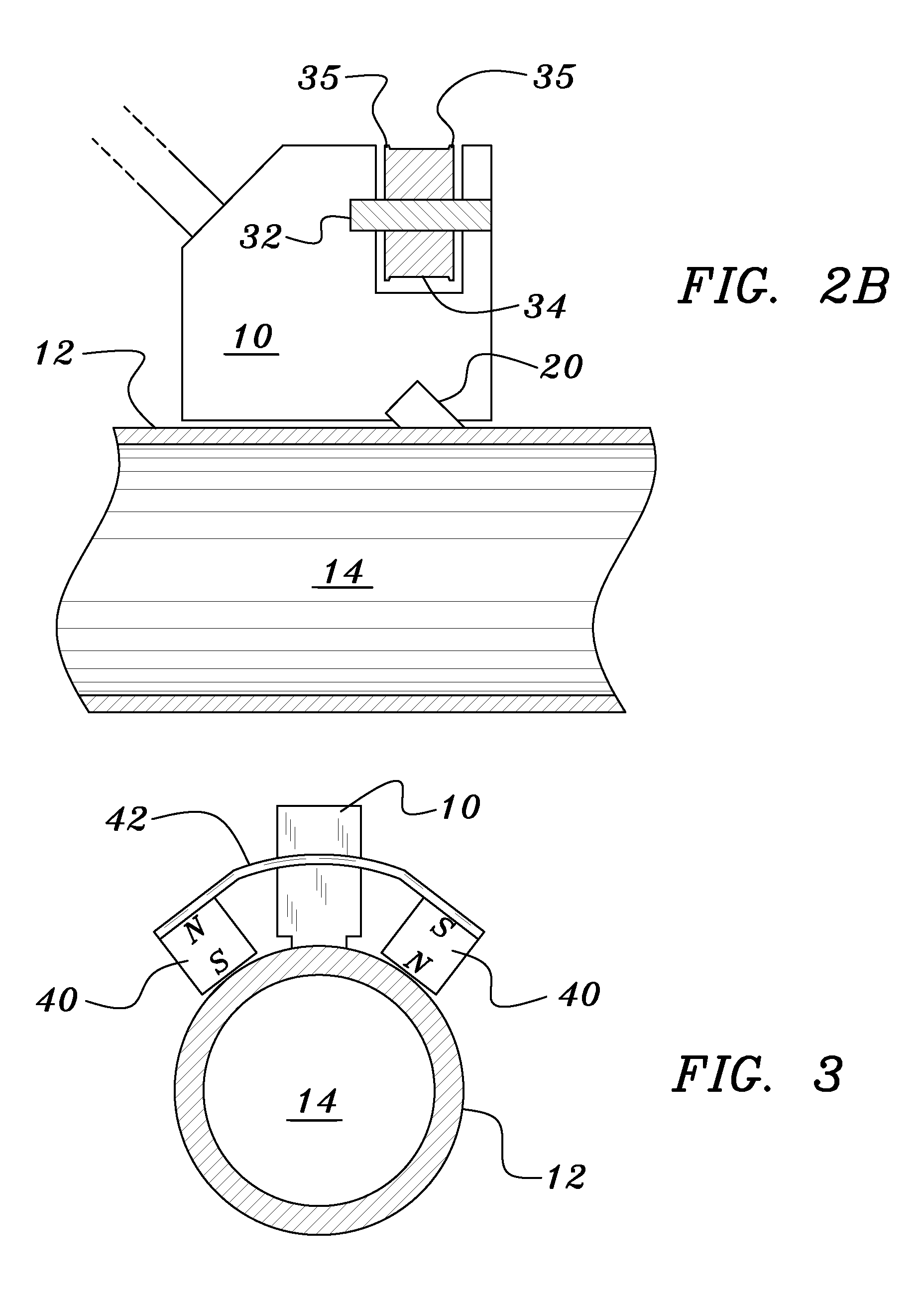
[0020]Turning now to FIG. 1, one finds a transducer housing 10 mounted on a pipe 12 which contains a fluid 14. The transducer housing 10 is pressed to the pipe 12 by the tension of a clamp band 16, arranged to loop around the pipe and the transd...


PUM


Abstract

Tangential forces present at the mating area between a clamp-on transducer and a pipe can be made very small in order to provide a higher quality, more stable acoustic coupling. In some cases this is accomplished by providing a low friction bearing on a surface of a transducer housing. This bearing may be a slippery surface portion, or may involve a rotary bearing mounted on the housing. In other cases, where a steel pipe is used, pairs of permanent magnets coupled by a yoke can provide the desired clamping force directed solely along a radius of the pipe.

Description

BACKGROUND OF THE INVENTION[0001]1. Field of the Invention[0002]The present application, which is a division of the inventor's U.S. Ser. No. 12 / 394,111, filed on Feb. 27, 2009 and now issued as U.S. Pat. No. 7,669,483, relates to acoustic transducer apparatus and methods for measuring a rate of flow of a fluid through a pipe. More specifically, the invention relates to arrangements in which ultrasonic transducers are clamped to an external surface of the pipe.[0003]2. Background Information[0004]Transit time flow meters used to measure the rate of flow of fluids through a pipe commonly employ clamp-on transducers attached against an external surface of the pipe. In these applications the transducers are commonly held against the pipe with screw-tensioned clamp bands. When these bands are tightened during installation, unbalanced frictional forces can move the transducer tangential to the pipe and can torque a portion of the transducer away from intimate acoustic contact with the pip...

Claims


Application Information

Patent Timeline
Patent Type & Authority Patents(United States)
IPC IPC(8): G01F1/66
CPCG01F1/662G01F1/667Y10T24/1441
Inventor FELLER, MURRAY F
Owner ONICON INC
Why Eureka
Try Eureka