Air-intake duct and air-intake structure

a technology of air intake duct and air intake structure, which is applied in the direction of combustion engine, combustion air/fuel air treatment, charge feed system, etc., can solve the problems of reducing air-intake efficiency, difficult to improve engine driving power characteristics, and air in the vicinity of an outer wall surface of air-intake duct not being smoothly suctioned into the air, so as to improve the efficiency of air intake to guide the air inside the air cleaner box to the throttle devi

Active Publication Date: 2012-04-10
KAWASAKI MOTORS LTD
View PDF25 Cites 6 Cited by
  • Summary
  • Abstract
  • Description
  • Claims
  • Application Information

AI Technical Summary

Benefits of technology

[0008]In accordance with the configuration, since the sub-wall having a smaller height is provided outside the main wall forming the main passage and the sub-passage is formed to extend along the outer wall surface of the main wall, air present in an outside region of the main wall of the air-intake duct can be suctioned through the sub-passage. In addition, since the sub-passage is not provided on the entire outer periphery of the main passage but is provided on one side of the main passage, the passage cross-sectional area of the air-intake passage can be increased without increasing a lateral width of the air-intake duct, as viewed from one side. Therefore, air-intake efficiency can be improved without increasing the size of the air-intake passage.
[0010]In accordance with the configuration, the air present in the region defined between the outer wall surface of the main wall of the air-intake duct and the inner wall surface of the air cleaner box can be suctioned through the sub-passage. In addition, since the sub-passage is positioned in close proximity to the air cleaner element, the air flowing within the air cleaner box can be guided smoothly to the sub-passage. As a result, air-intake efficiency of guiding the air inside the air cleaner box to the throttle device can be improved.

Problems solved by technology

However, air in the vicinity of an outer wall surface of the air-intake duct is not smoothly suctioned into the air-intake duct through an upstream opening due to the presence of the outer wall surface.
This results in reduced air-intake efficiency, making it difficult to improve an engine driving power characteristic.
However, since the motorcycle or the like has a limited vehicle body width, it is undesirable to increase the size of the component mounted therein.

Method used


Image

  • Air-intake duct and air-intake structure
  • Air-intake duct and air-intake structure
  • Air-intake duct and air-intake structure

Examples


embodiment 1

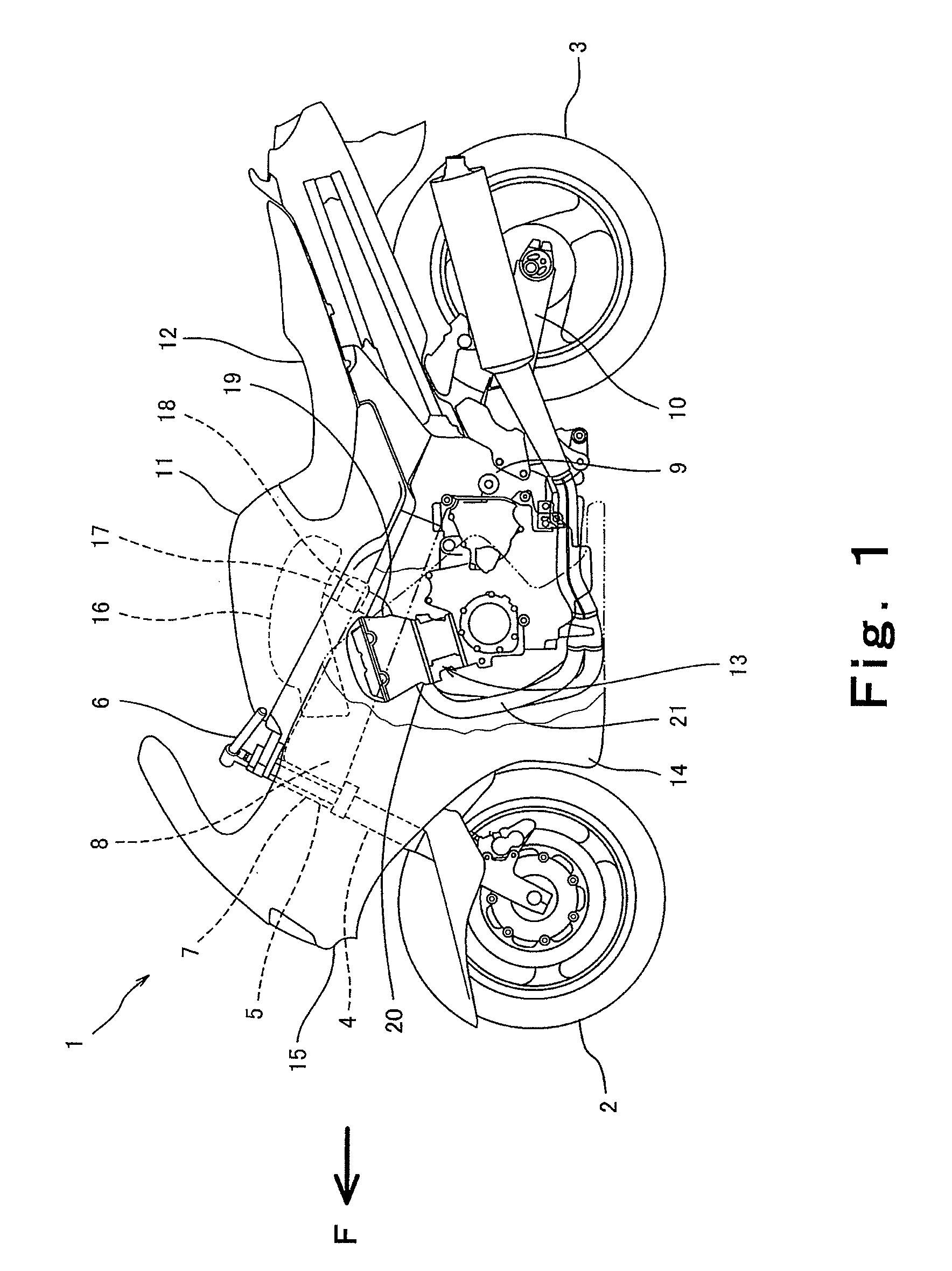
[0029]FIG. 1 is a left side view of a motorcycle 1 according to Embodiment 1 of the present invention. As shown in FIG. 1, the motorcycle 1 includes a front wheel 2 and a rear wheel 3. The front wheel 2 is rotatably mounted to the lower portion of a front fork 4 extending substantially vertically. A bar-type steering handle 6 extending rightward and leftward is mounted to the upper portion of the front fork 4 via a steering shaft 5. The steering shaft 5 is rotatably supported by a head pipe 7 forming a part of a frame. A pair of right and left main frame members 8 extends rearward from the head pipe 7. Pivot frame members 9 respectively extend downward from the rear portions of the main frame members 8. A swing arm 10 is pivotally mounted at the front end portion thereof to each of the pivot frames 9. The rear wheel 3 is rotatably mounted to the rear end portions of the swing arms 10.

[0030]A fuel tank 11 is provided above the main frame members 8. A seat 12 which is straddled by the...

embodiment 2

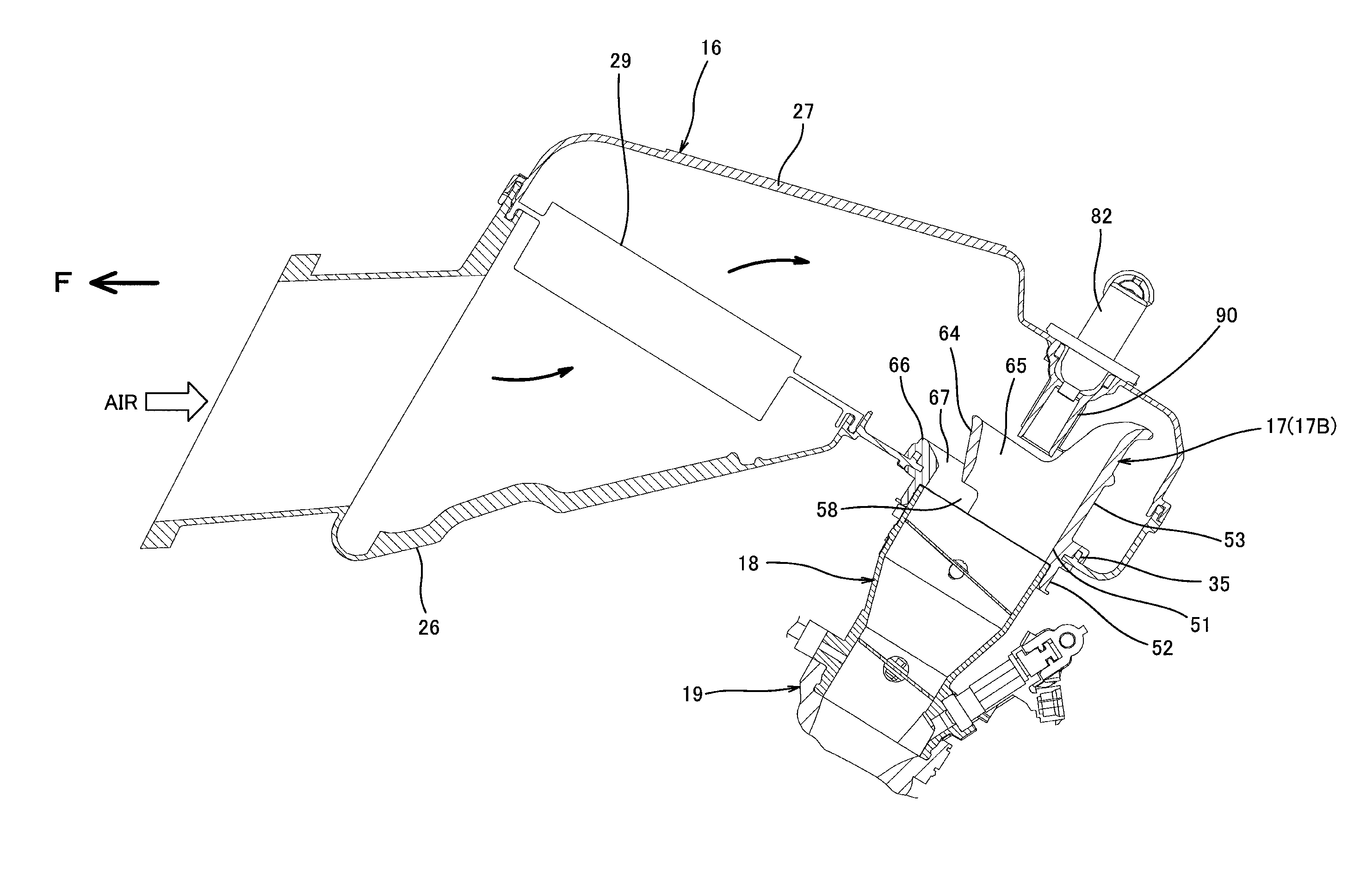
[0072]FIG. 11 is an exploded perspective view of an air-intake duct 70 according to Embodiment 2 of the present invention. As shown in FIG. 11, the air-intake duct 70 of this embodiment includes a duct base 71 and an attachment member 72. The same components as those of the above-described air-intake ducts 17A and 17B are designated by the same reference characters and will not be described in detail.

[0073]The duct base 71 has a main wall 54 identical to that of the air-intake duct 17A and a sub-wall 66 identical to that of the air-intake duct 17B. That is, the protruding amount of the sub-wall 66 in an upward direction is much smaller than the protruding amount of the main wall 54 in an upward direction. The attachment member 72 includes a tubular ring portion 73 with a smaller height and a semi-tubular extension portion 74 protruding upward from the front half portion of the ring portion 73. The extension portion 74 has a funnel shape with a diameter increasing in an upward direct...

embodiment 3

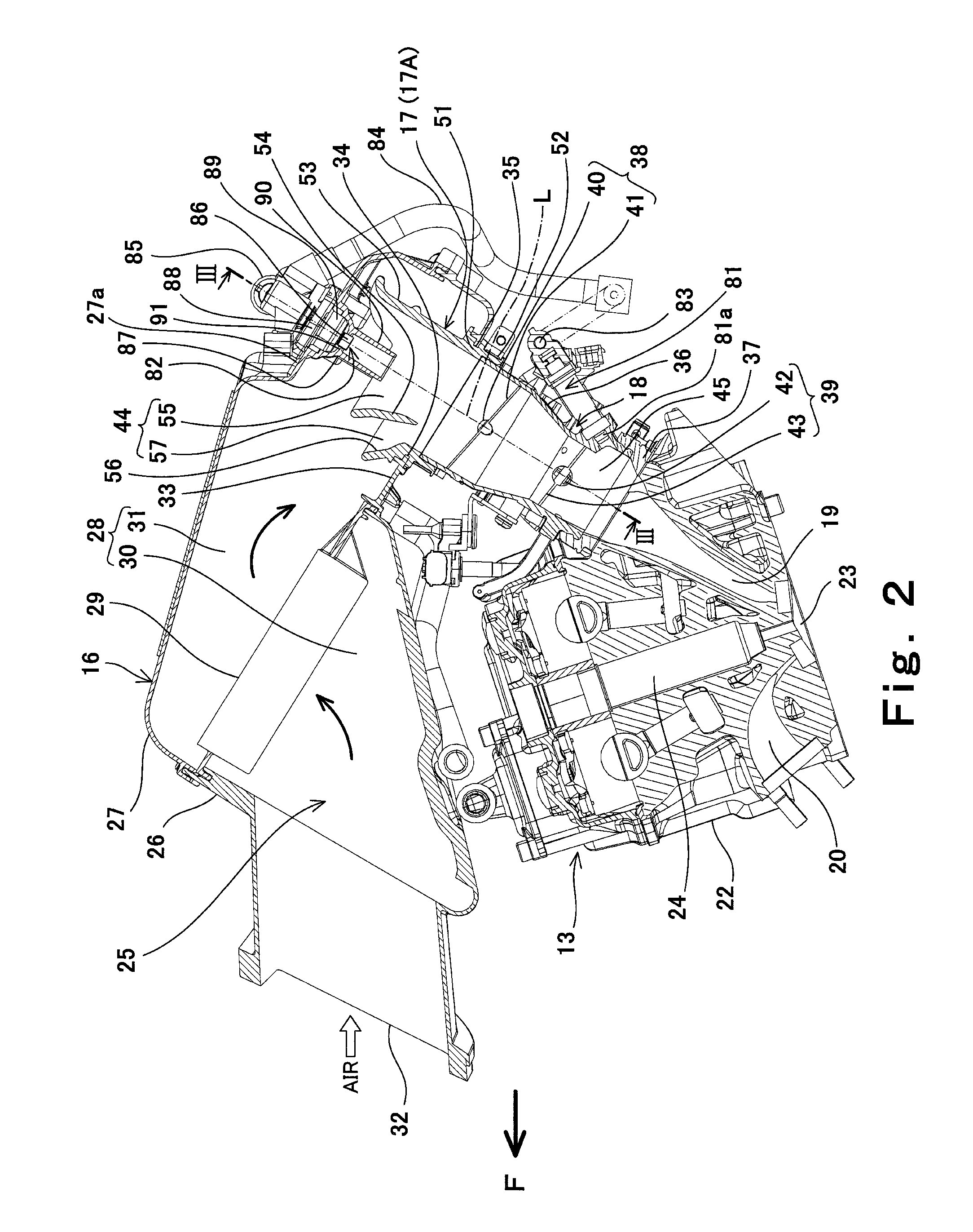
[0076]FIG. 14 is a cross-sectional view showing an air-intake structure according to Embodiment 3 of the present invention, as viewed from a right side. The same components as those of the above described air-intake structure are designated by the same reference numerals and will not be described.

[0077]As shown in FIG. 14, the upstream injector 82 is retained by a boss 89 of the stay 88, and the center axis of the upstream injector 82 substantially conforms to the center axis of an inner passage 144 of an air-intake duct 117. It should be noted that the inner passage 144 of the air-intake duct 117 is not divided into a main passage and a sub-passage unlike Embodiment 1 and Embodiment 2.

[0078]A cap member 191 is fitted to an upper case 127 of an air cleaner box 116 such that the cap member 191 covers the lower opening of the injector mounting member 187. A cylindrical fuel guide member 190 is fitted to the lower end portion of the cap member 191. The cap member 191 is made of an elas...


PUM


Abstract

An air-intake duct of the present invention, configured to guide air to a throttle device coupled to an engine, includes a main wall forming a main passage; and a sub-wall provided outside the main wall to form a sub-passage; wherein the sub-wall has a height smaller than a height of the main wall; and wherein the sub-passage is defined by an inner wall surface of the sub-wall and an outer wall surface of the main wall and is disposed on one side in a direction substantially perpendicular to a passage axis of the main passage.

Description

CROSS REFERENCE TO RELATED APPLICATION[0001]This application claims priority to and the benefit of Japanese Patent Application No. 2008-236788 filed on Sep. 16, 2008, and Japanese Patent Application No. 2008-238318 filed on Sep. 17, 2008, the entire disclosures of which are incorporated herein by reference.BACKGROUND ART[0002]1. Field of the Invention[0003]The present invention relates to an air-intake duct and an air-intake structure for guiding air to a throttle device coupled to an engine.[0004]2. Description of the Related Art[0005]As disclosed in, for example, Japanese Laid-Open Patent Application Publication No. 2006-90298, a so-called double injector engine including two fuel injectors in an air-intake passage is known as a high driving power engine mounted in a motorcycle or the like. One of the fuel injectors is attached to a throttle device at a downstream side of a throttle valve, while the other fuel injector is attached to an air cleaner box to inject a fuel to an upstr...

Claims


Application Information

Patent Timeline
Patent Type & Authority Patents(United States)
IPC IPC(8): F02M35/10
CPCF02M35/024F02M35/10032F02M35/10052F02M35/10216F02M35/10262F02M35/10354F02M35/162Y02T10/146Y02T10/12
Inventor MATSUDA, YOSHIHARUMATSUMOTO, TAKAFUMIYOKOYAMA, NAOKI
Owner KAWASAKI MOTORS LTD
Why Eureka
Try Eureka