Method and apparatus for controlling temperature

a technology of controlling temperature and temperature, applied in the direction of domestic cooling apparatus, lighting and heating apparatus, instruments, etc., can solve the problems of occupying valuable test equipment time, affecting the efficiency of cycling, and affecting the accuracy of cycling results

Active Publication Date: 2012-04-10
CENTIPEDE SYST
View PDF46 Cites 29 Cited by
  • Summary
  • Abstract
  • Description
  • Claims
  • Application Information

AI Technical Summary

Problems solved by technology

In addition, functional testing is performed on relatively expensive test equipment, and time taken to carry out such testing is important for economic reasons.
The use of such multiple test temperatures, and condensation of water at low temperatures, renders a thermal soak step impractical for helping to establish such multiple test temperatures.
In addition, increasingly, DUTs are cycled through a set of test temperatures while they are mounted on a test head, which cycling takes up valuable test equipment time.
This method is inefficient in that the test head is both heated and cooled at the same time.
Further, compromises in design that enable resistive heating to change the temperature of the test head also act to reduce the thermal efficiency of the test head.
In addition, the method of first cooling and then heating a flow of air is inefficient, and limits the efficacy of the method.
In further addition, the large amount of energy expended in both heating and cooling the air (or other thermal transfer fluid) limits the amount of air that can be processed in a practical system.
However, because a hot thermal transfer fluid must be mixed with a cold thermal transfer fluid to obtain a thermal transfer fluid having an intermediate temperature, this mixing process is inefficient.

Method used


Image

  • Method and apparatus for controlling temperature
  • Method and apparatus for controlling temperature
  • Method and apparatus for controlling temperature

Examples


Embodiment Construction

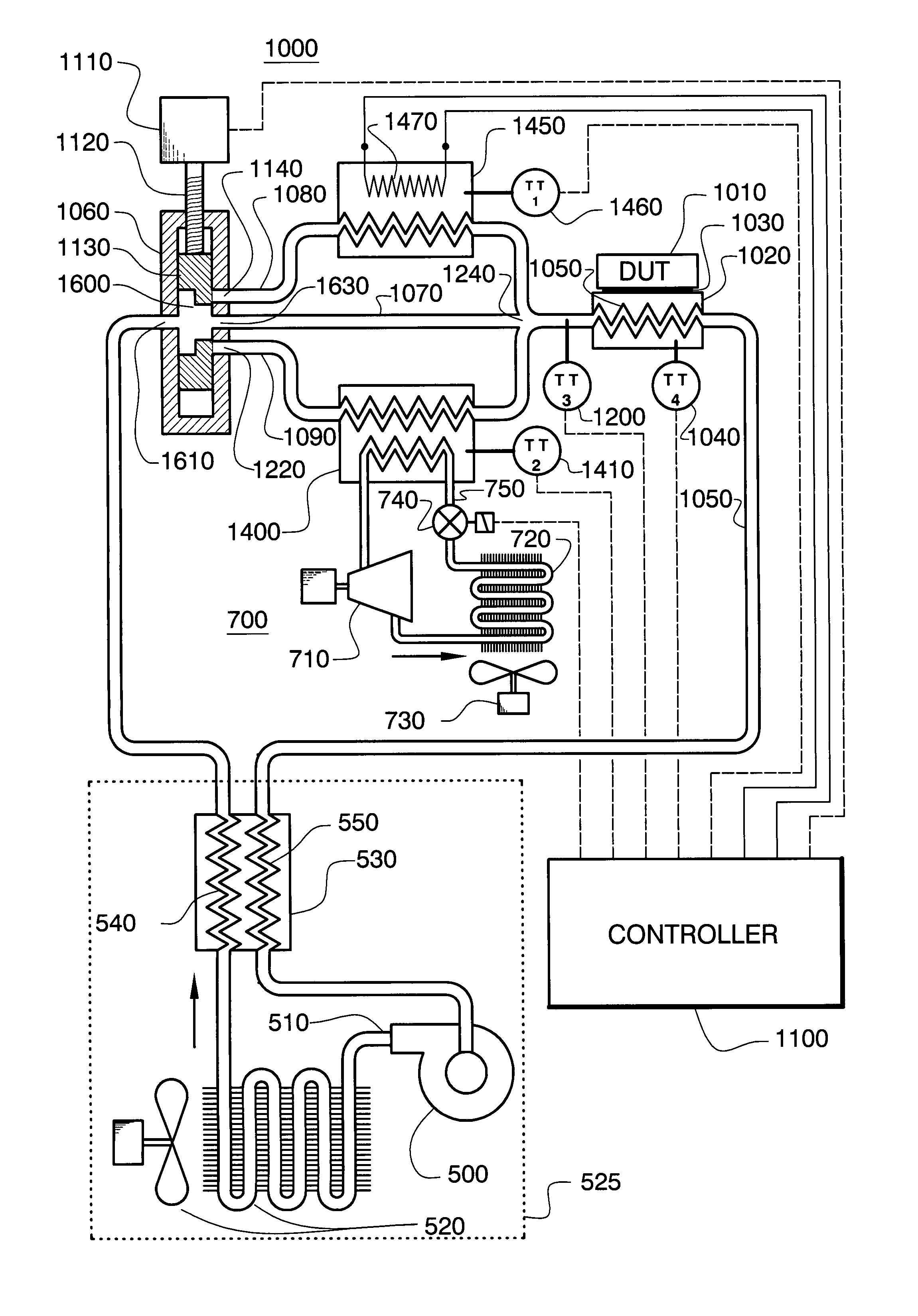
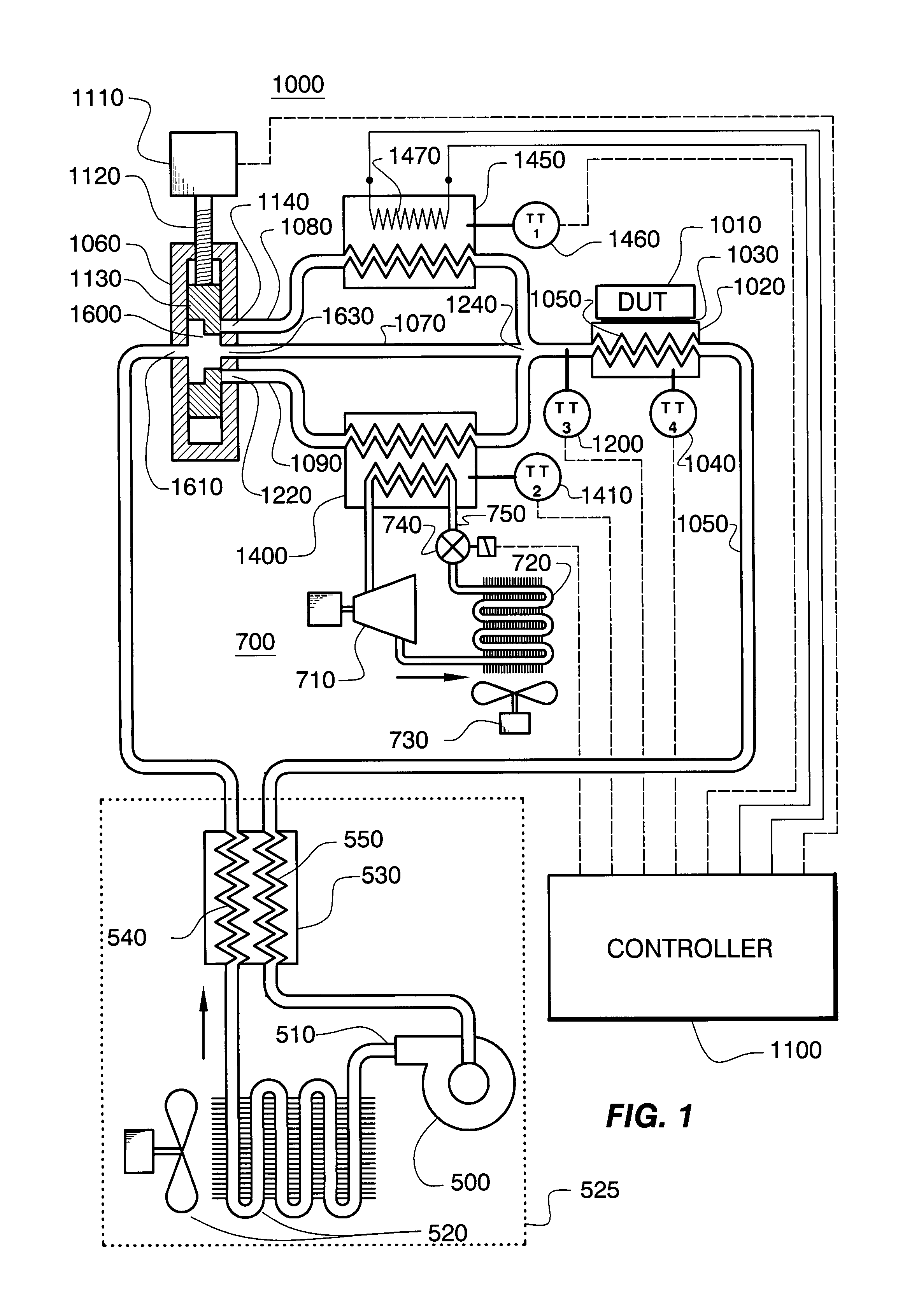
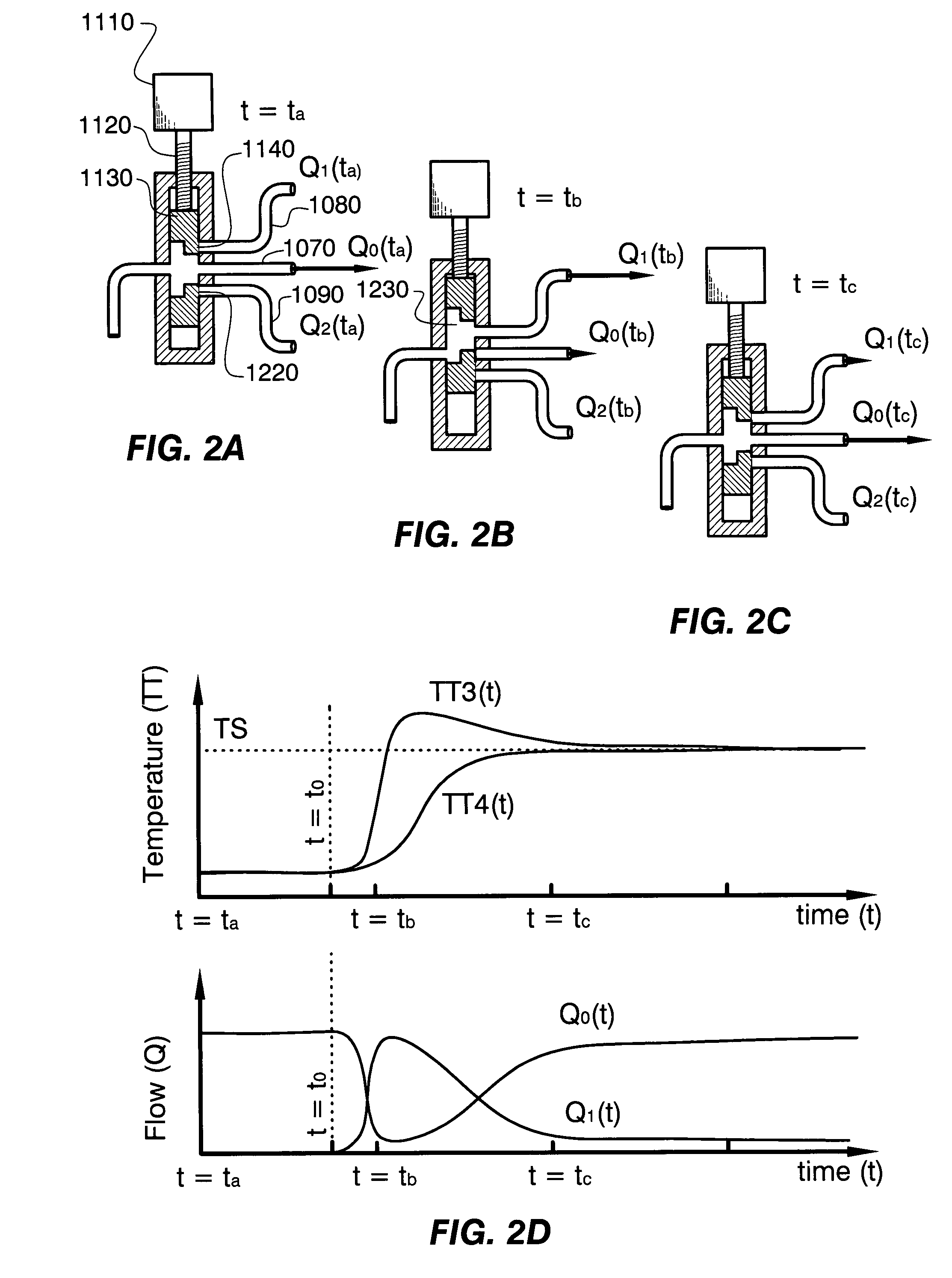
[0014]FIG. 1 is a schematic representation of apparatus 1000 that is fabricated in accordance with one or more embodiments of the present invention, which apparatus 1000 is useful to control temperature (for example and without limitation, set and maintain temperature) of device under test 1010 (“DUT 1010”) (such as, for example and without limitation, a microelectronic device and more specifically, a semiconductor integrated circuit). To perform testing using apparatus 1000: (a) DUT 1010 is mounted in a fixture, for example and without limitation, a socket, that provides signal contact, for example and without limitation, electrical contact, between DUT 1010 and automatic test equipment (“ATE”), for example and without limitation, electronic circuitry that provides test signals to, and receives responses from, DUT 1010; and (b) DUT 1010 is maintained in good thermal contact with thermal head 1020 that controls the temperature of DUT 1010.

[0015]In accordance with one or more embodim...


PUM


Abstract

Apparatus to control a temperature of a device that includes: a thermal head adapted to be thermally contacted to the device; a combined path to the thermal head; a first path maintained at a first temperature and connected to the combined path; a second path maintained at a second temperature different from the first temperature and connected to the combined path; a third path connected to the combined path; a pump assembly operable to circulate thermal transfer fluid: from the thermal head, through each of the first, second and third paths, from each of the first, second and third paths, through the combined path, and from the combined path, to and through the thermal head; and a valve assembly operable to control amounts of thermal transfer fluid that flow into the first and second paths, thereby controlling the temperature.

Description

TECHNICAL FIELD OF THE INVENTION [0001]One or more embodiments of the present invention relate to method and apparatus for controlling temperature, and more specifically to method and apparatus for controlling temperature of an electronic device during testing.BACKGROUND OF THE INVENTION [0002]Electronic devices such as semiconductor integrated circuits (“ICs”) are typically tested under conditions that include, particularly for complex devices, several temperatures (for example, including temperature extremes). In addition, functional testing is performed on relatively expensive test equipment, and time taken to carry out such testing is important for economic reasons. Thus, time taken to establish test temperatures ought to be minimized to minimize testing time and cost entailed in using such test equipment.[0003]In common testing practice, devices under test (“DUTs”) are brought to a test temperature in a thermal soak step in a test sequence. In more recent testing practice, test...

Claims


Application Information

Patent Timeline
Patent Type & Authority Patents(United States)
IPC IPC(8): F25B29/00F28F7/00F28F27/00F28F27/02
CPCF25B49/02F25D19/00F24H9/00F25B29/00F28F27/00F25B7/00F25B2400/01F25B2600/2521F25D17/02H01L23/473H01L2924/0002H01L2924/1433H01L2924/00G05D23/1931
Inventor DI STEFANO, THOMAS H.
Owner CENTIPEDE SYST
Why Eureka
Try Eureka