Multiple disc clutch apparatus

a technology of clutches and discs, applied in the direction of clutches, friction clutches, freewheel clutches, etc., can solve problems such as feeling, and achieve the effect of preventing a clutch center member from falling and improving accuracy

Active Publication Date: 2012-04-10
HONDA MOTOR CO LTD +1
View PDF12 Cites 6 Cited by
  • Summary
  • Abstract
  • Description
  • Claims
  • Application Information

AI Technical Summary

Benefits of technology

[0006]One or more embodiments of the invention provide a multiple disc clutch apparatus which can prevent a fall of a clutch center member and can improve accuracy with which the clutch is engaged and disengaged.

Problems solved by technology

However, this clearance so provided offsets a rotating axis of the clutch center member with respect to a rotating axis of the clutch inner member, and this causes the clutch center member to fall (incline), leading to the possibility that the feeling is affected which is felt by the driver when he or she engages or disengages the clutch.

Method used


Image

  • Multiple disc clutch apparatus
  • Multiple disc clutch apparatus
  • Multiple disc clutch apparatus

Examples


Embodiment Construction

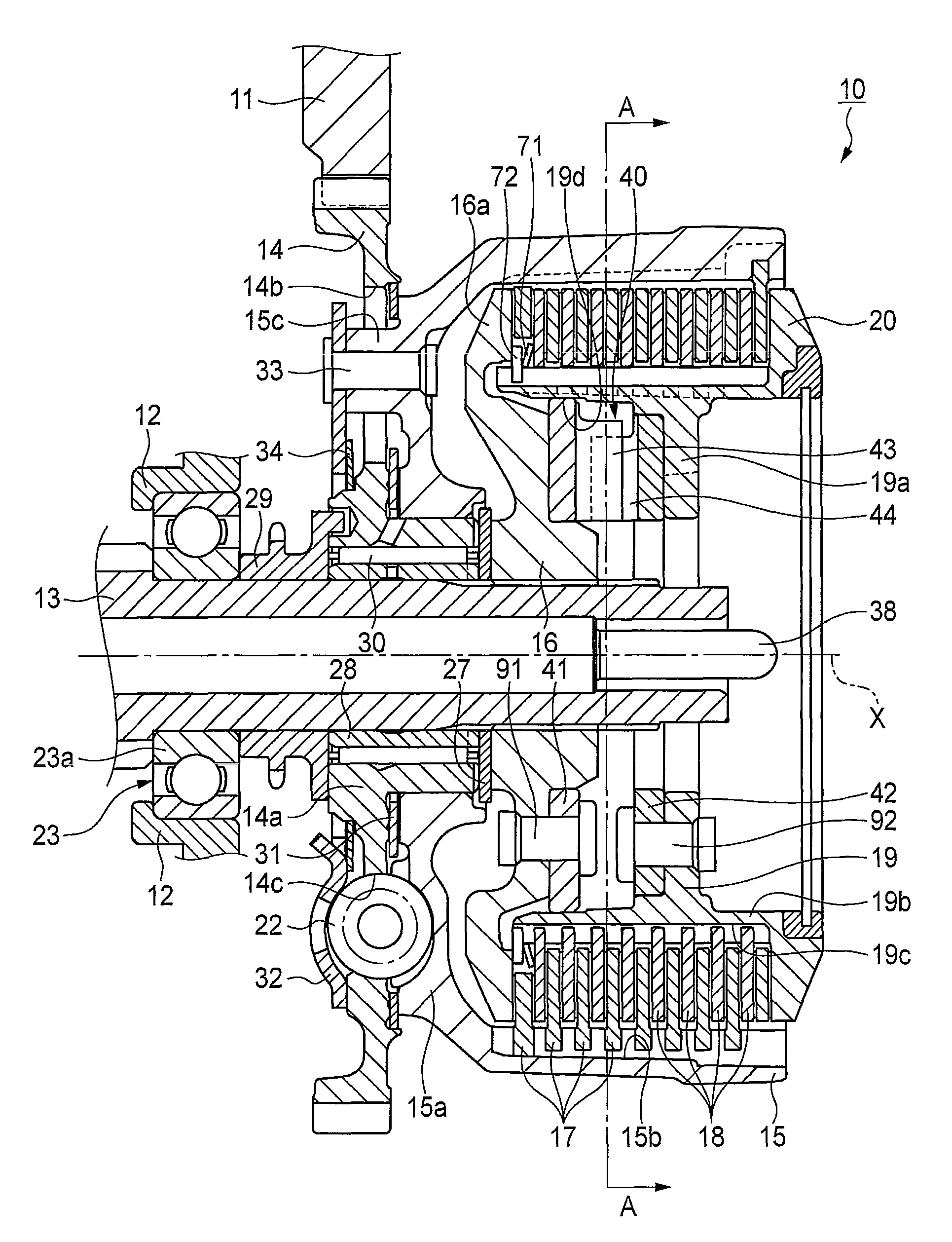
[0028]An exemplary embodiment of a multiple disc clutch apparatus according to the invention will be described in detail based on accompanying drawings. Note that the drawings are to be seen in a direction in which given reference numerals look normal.

[0029]As is shown in FIG. 1, a driving force outputted from a crankshaft, not shown, is transferred to a main shaft 13 of a transmission which is supported rotatably on a crankcase 12 by way of a drive gear 11 which is provided on the crankshaft, not shown, a driven gear 14 which is supported rotatably on the main shaft 13 and which meshes with the drive gear 11, and a multiple disc clutch apparatus 10 of the embodiment which is provided between the driven gear 14 and the main shaft 13.

[0030]As is shown in FIG. 1, the multiple disc clutch apparatus 10 of the embodiment includes a clutch outer member 15 which is coupled to the driven gear 14, which acts as an input member, a clutch inner member 16 which is fixed to the main shaft 13, wh...


PUM


Abstract

In a multiple disc clutch apparatus 10, a cam member 41 which is disposed on a side of a clutch inner member 16 is formed into an annular shape. The cam member 41 extends in a radial direction so that an outer circumferential surface of the cam member 41 is brought into abutment with a cylindrical face 19d on an inner circumferential surface of a clutch center member 19.

Description

BACKGROUND OF THE INVENTION[0001]1. Field of the Invention[0002]The present invention relates to a multiple disc clutch apparatus which transfers or interrupts a driving force from an input member and more particularly to a multiple disc clutch apparatus which includes a cam mechanism for suppressing an action of a reverse driving force from an output shaft towards the input member side.[0003]2. Background Art[0004]There is known, as a conventional multiple disc clutch apparatus, a multiple disc clutch apparatus provided with an clutch outer member which is coupled to an input member, a clutch inner member which is fixed to an output member, a plurality of primary friction discs which are brought into engagement with the clutch outer member so as not to rotate relatively, a plurality of secondary friction discs which are disposed alternately with the primary friction discs in an axial direction, a clutch center member with which the secondary friction discs are brought into engageme...

Claims


Application Information

Patent Timeline
Patent Type & Authority Patents(United States)
IPC IPC(8): F16D13/52F16D43/21
CPCF16D13/52F16D13/56F16D2013/565
Inventor SUZUTA, MASAYOSHISENMYO, HIDEONAGAHASHI, YOSHIKIYONEYAMA, MASAKIWAKABAYASHI, SHINYAYAMAMOTO, KAZUMITSUOTSUKA, HISAOFURUYA, MASASHIORI, HIROSHISEGAMI, HIDEAKIYOSHIMOTO, KATSU
Owner HONDA MOTOR CO LTD
Why Eureka
Try Eureka