Scroll compressor for preventing performance deterioration and variation due to gas leakage

a technology of scroll compressor and gas leakage, which is applied in the direction of machines/engines, rotary/oscillating piston pump components, liquid fuel engines, etc., can solve the problems of thermal deformation in the vicinity of the step portion, performance deterioration or performance variation, and insufficient portion function, so as to prevent performance deterioration and performance variation, performance improvement, and performance deterioration

Active Publication Date: 2012-04-10
MITSUBISHI HEAVY IND LTD
View PDF10 Cites 2 Cited by
  • Summary
  • Abstract
  • Description
  • Claims
  • Application Information

AI Technical Summary

Benefits of technology

[0008]The disclosure in Patent Document 2 is intended to suppress the influence of thermal deformation of the tip seal occurring at the spiral starting end on the inner peripheral end of the spiral wrap of a typical scroll compressor to obtain a uniform sealing property, and is not intended to overcome the challenge of reducing gas leakage from the top surface of the wrap on the outer peripheral side of the step portion of the spiral wrap of a scroll compressor capable of three-dimensional compression. Patent Document 2 neither suggests nor teaches, at all, how the step portions provided on the top surface and bottom surface of the spiral wrap are thermally influenced during operation of the compressor, and how the thermal influence on the step portions influences gas leakage from the top surface of the wrap on the outer peripheral side of the step portion, i.e., the compression performance.
[0034]According to the present invention, the tip seal on the outer peripheral side of the step portion can be made to function normally, the tip seal can be urged against the bottom surface of the counterpart scroll member by back-pressure, and the top surface of the spiral wrap can be assuredly sealed. Accordingly, it is possible to prevent performance deterioration and performance variation due to gas leakage occurring on the outer peripheral side of the step portion of the spiral wrap to achieve stabilization and improvement of the performance of the scroll compressor capable of three-dimensional compression.

Problems solved by technology

However, in the disclosure in Patent Document 1, there are concerns about the problem of processability of a high-pressure introduction path provided on the spiral wrap and the influence of the introduction path on the wrap strength.
Further, a countermeasure against thermal deformation in the vicinity of the step portion, at which the height of the spiral wrap increases, is insufficient.
Accordingly, the problem remains that, unless a countermeasure sufficiently taking into consideration thermal deformation occurring at the step portion is taken, a movable gap of the tip seal is narrowed, whereby even if a high-pressure introduction path is provided, the tip seal provided on the outer peripheral side of the step portion cannot function sufficiently, causing performance deterioration or performance variation due to gas leakage.

Method used


Image

  • Scroll compressor for preventing performance deterioration and variation due to gas leakage
  • Scroll compressor for preventing performance deterioration and variation due to gas leakage
  • Scroll compressor for preventing performance deterioration and variation due to gas leakage

Examples


first embodiment

[0068]A first embodiment of the present invention will be described below with reference to FIGS. 1 to 8.

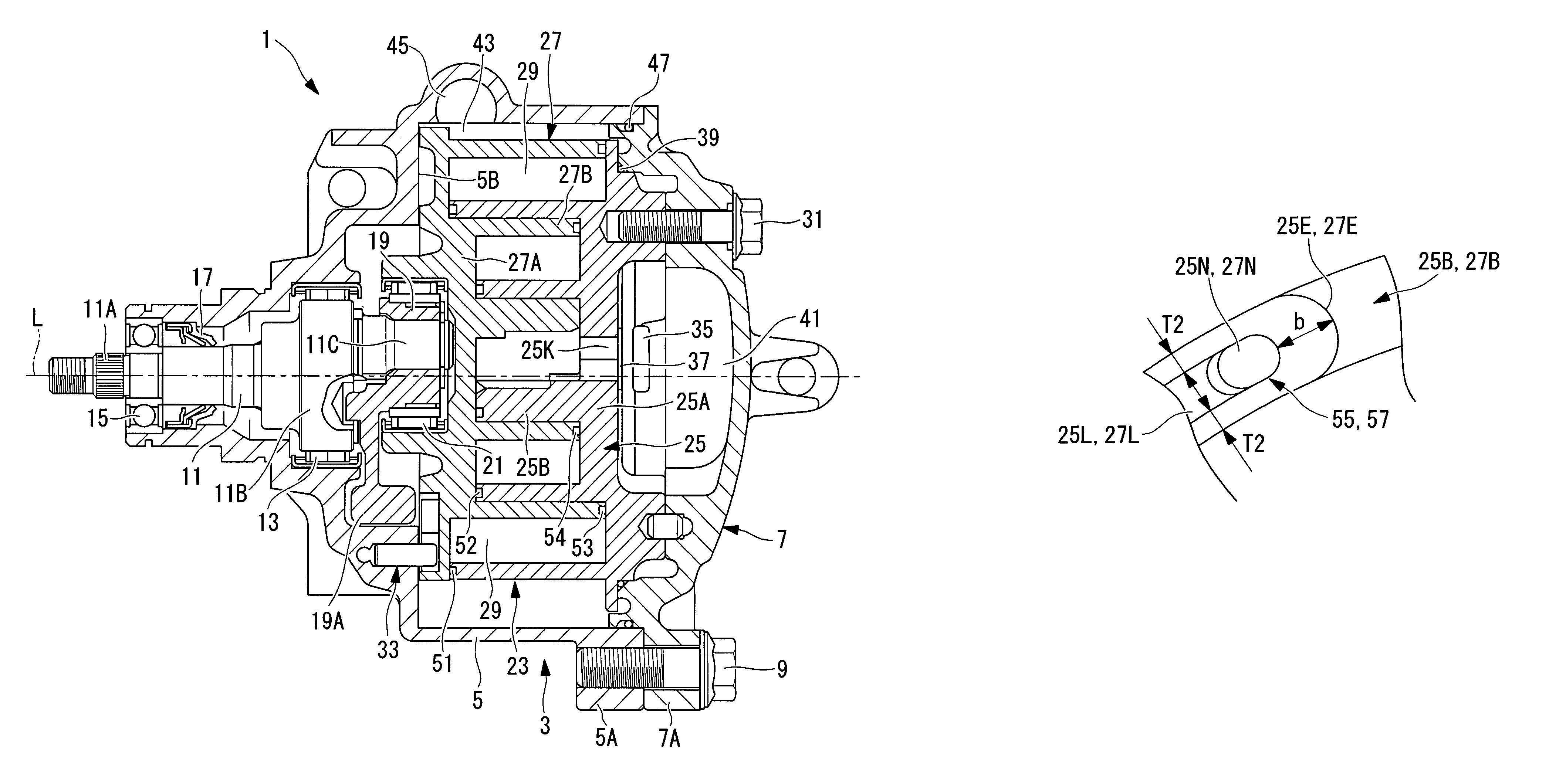
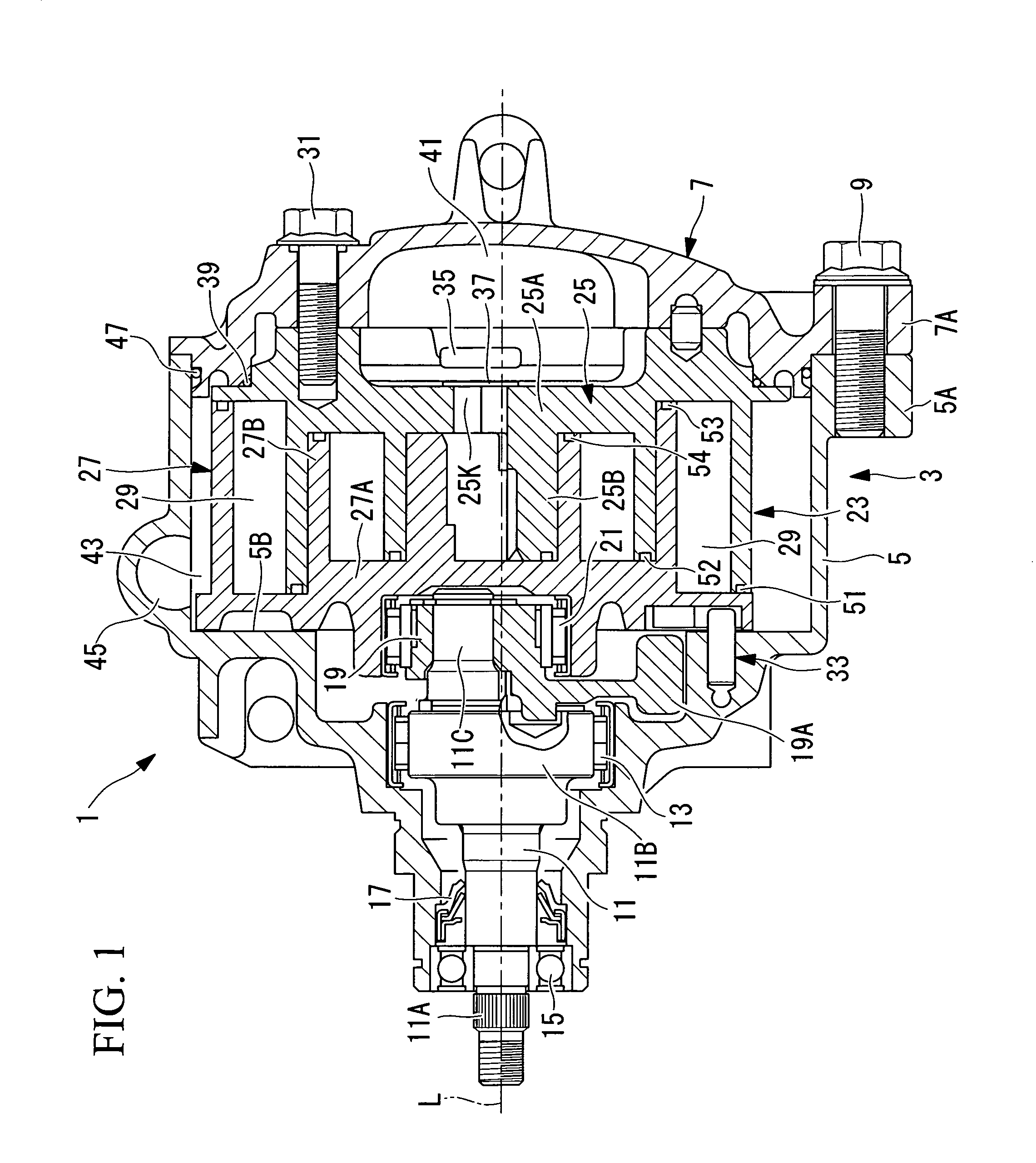
[0069]FIG. 1 is a longitudinal sectional view of a scroll compressor 1 according to the first embodiment of the present invention. The scroll compressor 1 has a housing 3 that generally defines the external shape thereof. The housing 3 is formed by integrally and securely fastening a front housing 5 and a rear housing 7 with bolts 9 (second bolt). The front housing 5 and the rear housing 7 have fastening flanges 5A and 7A, respectively, that are formed integrally therewith at an equally spaced plurality of positions, for example, four positions, on the circumferences thereof. By fastening these flanges 5A and 7A with the bolts 9, the front housing 5 and the rear housing 7 are integrally connected.

[0070]Inside the front housing 5, a crankshaft 11 is supported via a main bearing 13 and a sub-bearing 15 in a rotatable manner about an axis L. One end (in the drawing, the left side) o...

second embodiment

[0096]A second embodiment of the present invention will be described below with reference to FIGS. 4A, 4B, and 4C.

[0097]This embodiment is different from the first embodiment in that the structure in the vicinity of the step portions 25E and 27E of the tip seal grooves 25L and 27L is further specified. Because the other points are the same as that according to the first embodiment, an explanation thereof will be omitted.

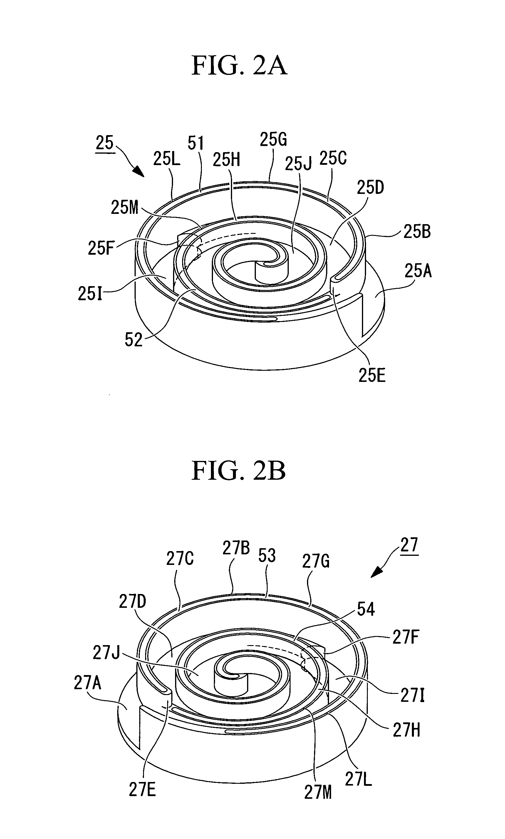
[0098]In this embodiment, as shown in FIGS. 4A, 4B, and 4C, the width of the edges formed at the ends of the step portions 25E and 27E of the tip seal grooves 25L and 27L is set wider than the width of the edge of the other portion, to increase the strength of the edges.

[0099]That is, the width, b, of the edges formed at the step-portion ends of the tip seal grooves 25L and 27L provided in the top surfaces 25G and 27G is set larger than the width, T2, of the edges formed along and on both sides of the tip seal grooves 25L and 27L, that is, b>T2.

[0100]It is preferable...

third embodiment

[0104]Next, a third embodiment of the present invention will be described with reference to FIGS. 9A and 9B.

[0105]This embodiment is different from the first embodiment in that the structure in the vicinity of the step portions 25E and 27E of the tip seal grooves 25L and 27L and the structure of the tip seals 51 and 53 are changed. Because the other points are the same as that according to the first embodiment, an explanation thereof will be omitted.

[0106]In this embodiment, as shown in FIGS. 9A and 9B, tip seal grooves 65L and 67L are formed in the top surfaces 25G and 27G on the outer peripheral side of the step portions 25E and 27E of the spiral wraps 25B and 27B such that they penetrate the step portions 25E and 27E. Tip seals 71 and 73 fitted to the tip seal grooves 65L and 67L are also provided such that they extend to the ends of the tip seal grooves 65L and 67L.

[0107]In addition, in the above-described structure, because the tip seals 71 and 73 slide out of the tip seal groo...


PUM


Abstract

In a scroll compressor configured to be capable of three-dimensional compression in a circumferential direction and a height direction of spiral wraps, in which top surfaces and bottom surfaces of spiral wraps (25B and 27B) are provided with step portions (25E and 27E) and the wrap height on the outer peripheral side of the step portion is made higher than the wrap height on the inner peripheral side, back-pressure introducing portions (55 and 57) where gaps between the back surfaces at step-portion ends of tip seals and groove bottom surfaces of tip seal grooves are made larger than a gap at the other portion are formed between the step-portion ends of tip seals (51 and 53) provided on top surfaces (25G and 27G) on the outer peripheral side of the spiral wraps and tip seal grooves (25L and 27L) to which the tip seals are fitted.

Description

TECHNICAL FIELD[0001]The present invention relates to a scroll compressor having a step portion on each of a top surface and a bottom surface of a spiral wrap, the wrap height of the spiral wrap on the outer peripheral side of the step portion is made higher than the wrap height on the inner peripheral side, so as to enable three-dimensional compression in a circumferential direction and a height direction of the spiral wrap.BACKGROUND ART[0002]As a scroll compressor whose compressor capacity can be increased without increasing the outside diameter of a scroll member, a scroll compressor has been proposed in which a top surface and a bottom surface of spiral wraps of a fixed scroll member and an orbiting scroll member, forming a pair, are each provided with a step portion, the wrap height of the spiral wraps on the outer peripheral side of the step portions is made higher than the wrap height on the inner peripheral side, so as to enable three-dimensional compression in a circumfere...

Claims


Application Information

Patent Timeline
Patent Type & Authority Patents(United States)
IPC IPC(8): F03C2/00F03C4/00F04C2/00
CPCF01C19/005F04C18/0215F04C18/0276F04C18/0284F04C27/005
Inventor FUJITA, KATSUHIROMORO, TOMOHISAHIRATA, HIROHUMIOHTA, MASAHIROWATANABE, KAZUHIDEKUWAHARA, TAKAYUKITAKEUCHI, MAKOTOUKAI, TETUZOU
Owner MITSUBISHI HEAVY IND LTD
Why Eureka
Try Eureka