Resistive actuator with dynamic variations of frictional forces

a friction force and actuator technology, applied in the direction of mechanical control devices, process and machine control, instruments, etc., can solve the problems of affecting the operation of the motor, and requiring a relatively large and expensive motor to generate the torque required,

Inactive Publication Date: 2012-04-10
IMMERSION CORPORATION
View PDF8 Cites 41 Cited by
  • Summary
  • Abstract
  • Description
  • Claims
  • Application Information

AI Technical Summary

Problems solved by technology

However, because a motor always adds energy to the system, it can become unstable.
Further, a motor-based actuator system requires a relatively large and costly motor to generate the required amount of torque.
One problem with known rotary knobs having a braking actuator system is that a magnetic air gap must be maintained between two metallic rigid devices.
This air gap must typically be maintained within a tight tolerance, thus making manufacturing of the device expensive and difficult.
Further, known rotary knobs with braking actuators typically only include one level of frictional braking.

Method used


Image

  • Resistive actuator with dynamic variations of frictional forces
  • Resistive actuator with dynamic variations of frictional forces
  • Resistive actuator with dynamic variations of frictional forces

Examples


Embodiment Construction

[0014]One embodiment is a rotary knob having a resistive actuator that includes a dynamic variation of frictional forces by varying the interfaces of surfaces.

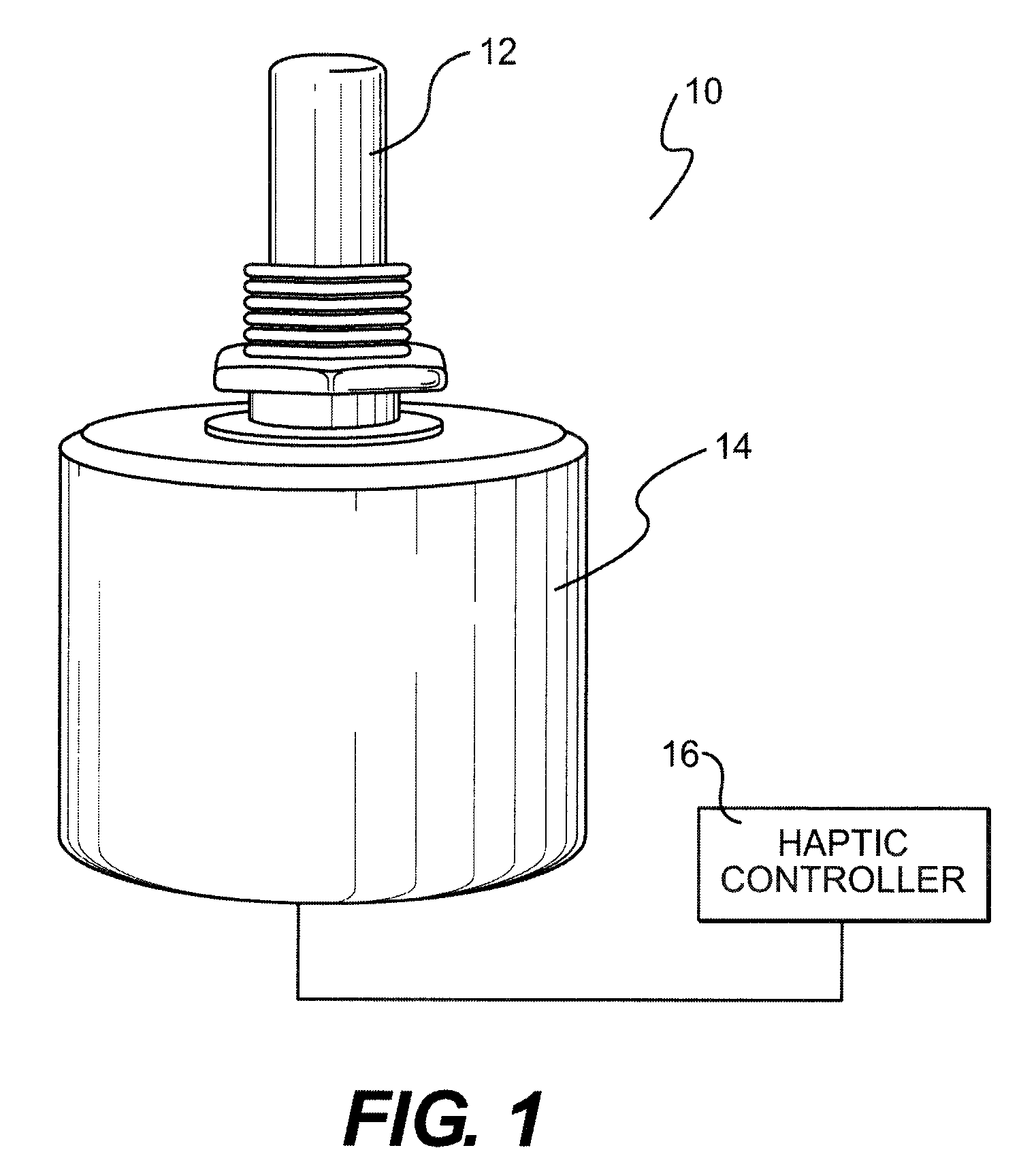
[0015]FIG. 1 is a perspective view of a rotary knob 10 in accordance with one embodiment. Rotary knob 10 includes a base 14, a rotating shaft 12, and a haptic controller 16. Rotating shaft 12 may be coupled to a knob or other device that can be rotated by a user. Controller 16 may include a processor and memory that stores instructions that are executed by the processor. Controller 16 generates haptic effects that are applied when rotating shaft 12 is rotated by a user. Controller 16 may be located external to base 14 as shown in FIG. 1, or internal to base 14.

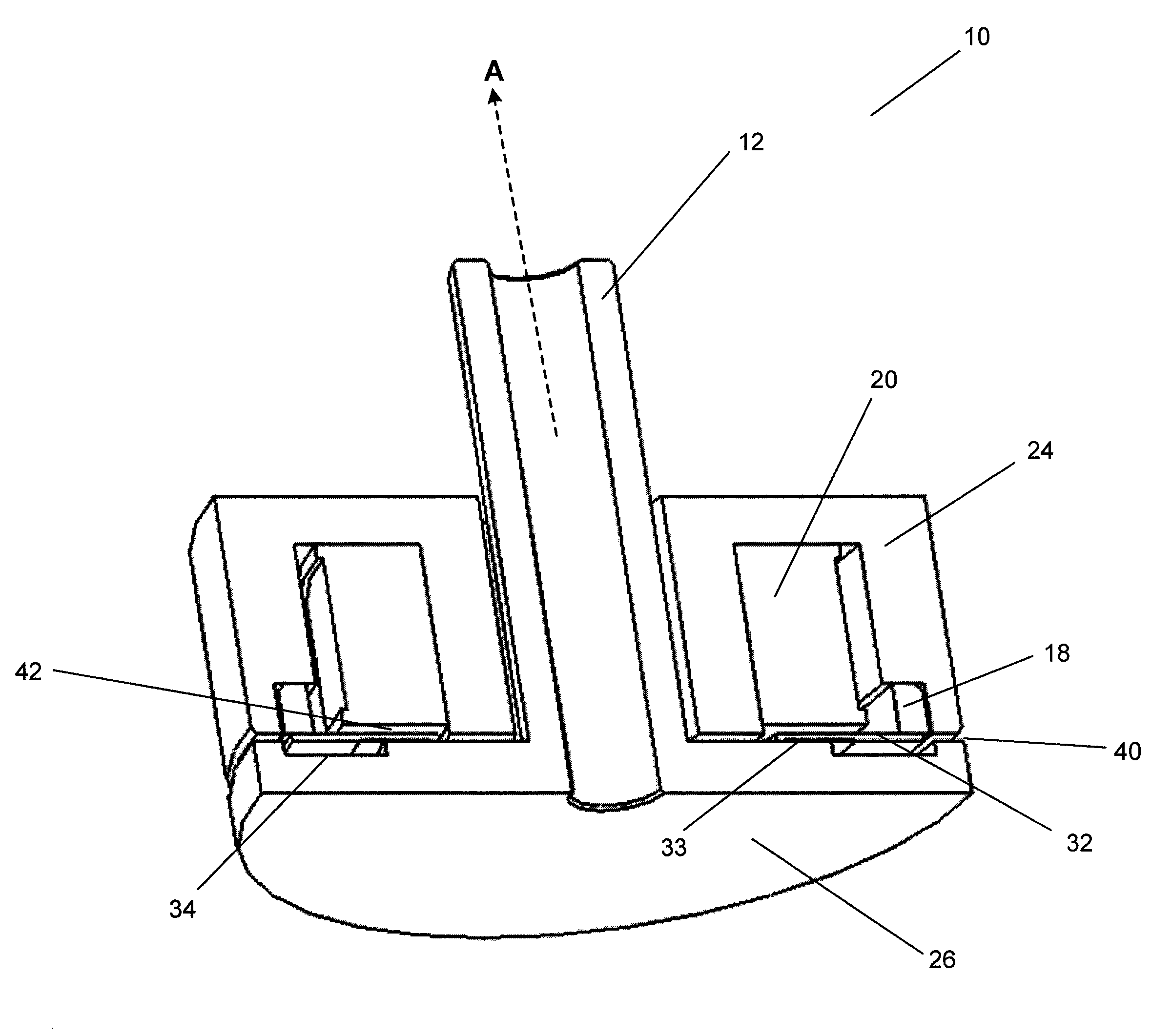
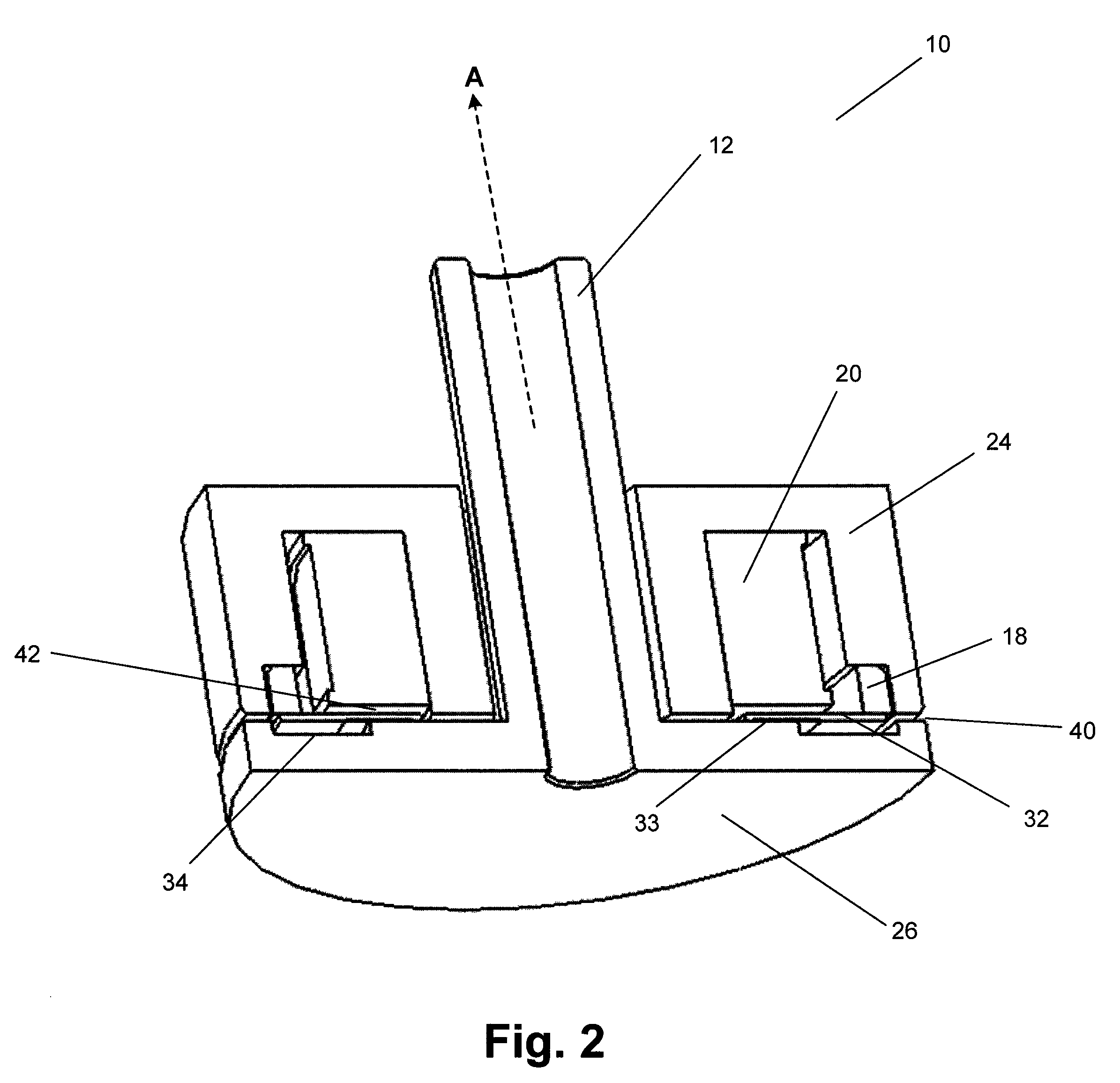
[0016]FIG. 2 is a cut-away perspective view of rotary knob 10 in accordance with one embodiment. Knob 10 includes shaft 12 which is coupled to a rotating circular disk 26 or any other type of rotating element. It one embodiment, circular disk 26 is formed from nickel-pla...


PUM


Abstract

A system for generating haptic effects on a rotary knob includes an electrical coil and a core. A first level of voltage is applied to the coil to enable a first surface interface having a first coefficient of friction and to generate a first haptic effect by varying the voltage. A second level of voltage is applied to the coil to enable a second surface interface having a second coefficient of friction that is greater than the first coefficient of friction and to generate a second haptic effect by varying the voltage.

Description

FIELD OF THE INVENTION[0001]One embodiment of the present invention is directed to haptic feedback. More particularly, one embodiment of the present invention is directed to a rotary knob having haptic feedback.BACKGROUND INFORMATION[0002]Electronic device manufacturers strive to produce a rich interface for users. Conventional devices use visual and auditory cues to provide feedback to a user. In some interface devices, kinesthetic feedback (such as active and resistive force feedback) and / or tactile feedback (such as vibration, texture, and heat) is also provided to the user, more generally known collectively as “haptic feedback” or “haptic effects”. Haptic feedback can provide cues that enhance and simplify the user interface.[0003]Haptic feedback has been implemented on rotary knobs and other types of electromechanical devices such as mechanical switches and encoders to create a flexible user interface. A wide variety of available haptic feedback, including detents, barriers and...

Claims


Application Information

Patent Timeline
Patent Type & Authority Patents(United States)
IPC IPC(8): G06F3/033
CPCG05G1/10G05G5/03G06F3/016G06F3/0362B60K37/06B60K2350/102B60K2370/126B60K2370/158
Inventor OLIEN, NEIL THOMAS
Owner IMMERSION CORPORATION
Why Eureka
Try Eureka