On-chip voltage supply scheme with automatic transition into low-power mode of MSP430

a technology of automatic transition and voltage supply, applied in the direction of power supply for data processing, instruments, computing, etc., can solve the problem of low power implementation, and achieve the effect of simple and robust structure and simplified operating mode control

Active Publication Date: 2012-04-17
TEXAS INSTR INC
View PDF9 Cites 4 Cited by
  • Summary
  • Abstract
  • Description
  • Claims
  • Application Information

AI Technical Summary

Benefits of technology

[0003]It is a general object of the present invention to provide an integrated electronic device including circuitry for providing a system supply voltage for different power requirements, which has a simplified operating mode control and seamless transition between the different power modes, and that has a simple and robust structure.
[0007]Preferably, the device further comprises a power on reset stage coupled to the supply system node. In this way, the state of the system can always be reset if, at start up, the device is in an indeterminate state. The high power stage can be also be adapted to receive an enable signal to be switched off in a power down mode, which allows a further power saving to be achieved.

Problems solved by technology

Furthermore, since there is only one startup when the system is powered on, a very low power implementation is possible.

Method used


Image

  • On-chip voltage supply scheme with automatic transition into low-power mode of MSP430
  • On-chip voltage supply scheme with automatic transition into low-power mode of MSP430

Examples


Embodiment Construction

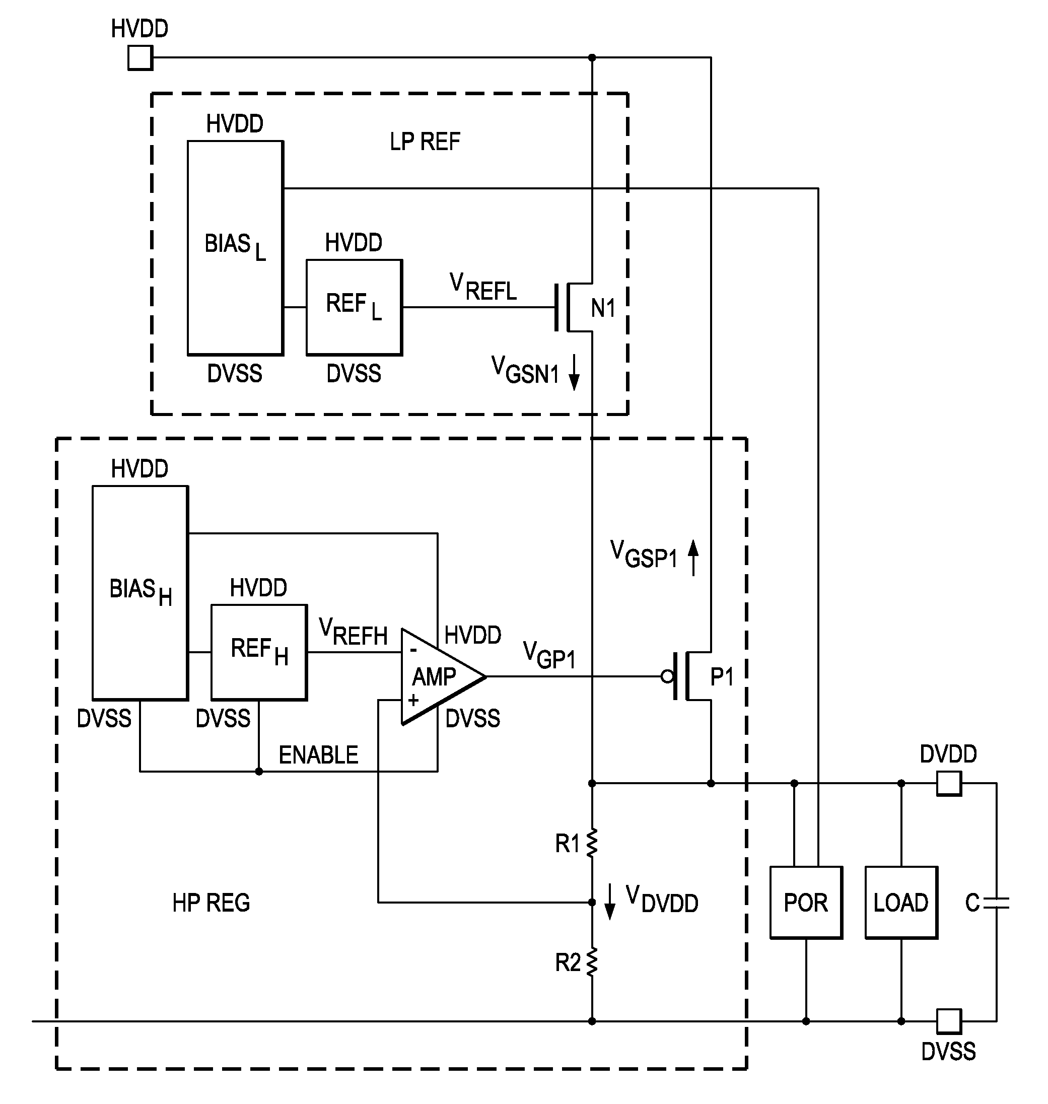
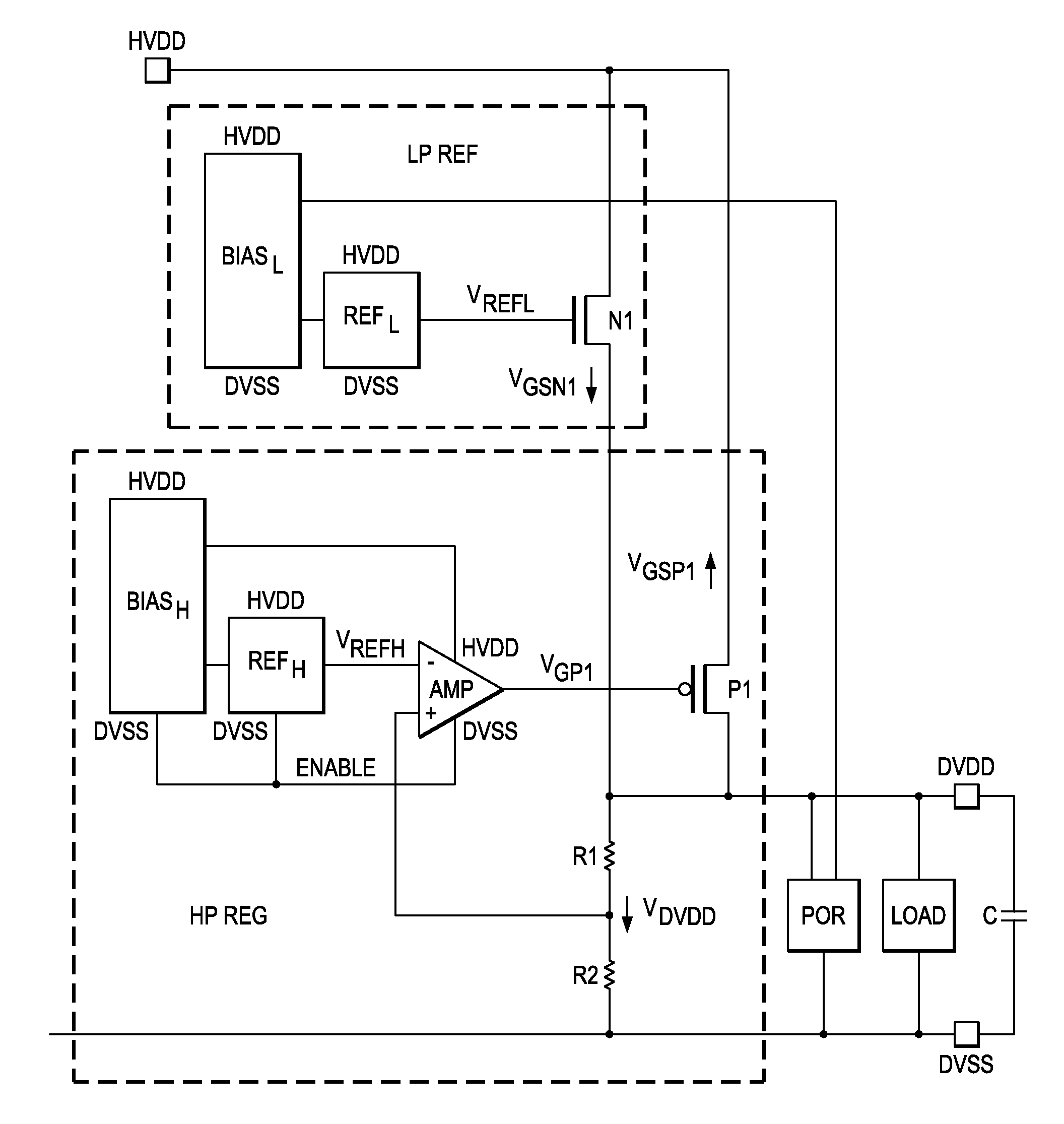
[0011]FIG. 1 shows a circuitry for providing a system supply voltage. A low power stage LP REF and a high power stage HP REG both have input nodes coupled to a primary power supply voltage rail HVDD. The output nodes of both the low power stage LP REF and the high power stage HP REG are coupled to a system supply node VDVDD, from which an output voltage is supplied to a load Load. The high power stage HP REG comprises an amplifier Amp, having a negative input operable to receive a reference voltage VREFH, which is supplied by enable mode circuitry shown schematically here as blocks BiasH and RefH. The enable mode circuitry also supplies the enablement pins of the amplifier Amp. The positive terminal of the amplifier Amp is also connected to the supply system node VDVDD via a resistive divider comprised of resistors R1 and R2 so that the amplifier Amp is operable to receive a feedback voltage from the supply system node VDVDD and acts as a comparator. The output voltage VGP1 of the a...


PUM


Abstract

An integrated electronic device includes circuitry for providing a system supply voltage from a primary power supply. The circuitry has a high power (HP) stage coupled to the primary power supply and having an output node coupled to a supply system node for providing a HP system supply voltage level and a HP output current such that the HP stage is configured to be active in a full power mode, and a low power (LP) stage coupled to the primary power supply and to the supply system node through a voltage follower for providing a LP supply voltage level and an LP output current such that the LP stage is configured to be active in a low power mode. The HP system supply voltage level is greater than the LP system supply voltage level and the voltage follower of the LP stage is adapted to switch off in response to a voltage level at the supply system node becoming greater than the HP system supply voltage level and to switch on in response to the voltage level at the supply system node becoming lower than the HP system supply voltage level.

Description

FIELD OF THE INVENTION[0001]The present invention generally relates to an integrated electronic device including circuitry for providing a system supply voltage from a primary power supply. More particularly, the present invention relates to circuitry having a high power stage and a low power stage for supplying a voltage to a microcontroller in both high power and low power modes.BACKGROUND OF THE INVENTION[0002]Most of today's electronic devices comprise microcontrollers for controlling the circuitry in such devices and storing data. Particularly in portable devices, minimizing power consumption is of the utmost importance, since the batteries used for the power supplies are required to have very long lives of several years. In order to save power, microcontrollers are configured to have a low power mode when the device needs only limited power or is inactive. However, in the low power mode, it is still required to save and retain data. For data retention and operation in many mic...

Claims


Application Information

Patent Timeline
Patent Type & Authority Patents(United States)
IPC IPC(8): G05F1/00
CPCG05F1/56G06F1/26G06F1/3203
Inventor ARNOLD, MATTHIAS
Owner TEXAS INSTR INC
Why Eureka
Try Eureka