Method for optical measurement of objects using a triangulation method

a triangulation method and object technology, applied in the field of optical measurement of the three dimensional geometry of objects, can solve the problems of image defects, inability to create several complete images of inability to measure objects on the fly,

Active Publication Date: 2012-04-17
SIRONA DENTAL SYSTEMS
View PDF22 Cites 87 Cited by
  • Summary
  • Abstract
  • Description
  • Claims
  • Application Information

AI Technical Summary

Benefits of technology

[0027]The advantage of the phase shift method is that, unlike assigning by counting or the binary code method, a measurement point is not assigned to a specific stripe and thus to a discrete coordinate, but a non-discrete coordinate of the measurement point is determined that can also be located between two stripes. Consequently, a higher degree of precision is achieved.
[0058]Photogrammetry involves a group of measuring methods to determine the spatial position and three-dimensional shape of an object from photographic images of the object taken from different directions. Usually, high-resolution digital cameras are used for creation of the photographic images. Photogrammetry is a computer-assisted technique in which 3D coordinates of object points are determined from the individual photographic images with the aid of pattern recognition and central projection. The supplementary images are thus imaged from different directions and an supplementary photogrammetric 3D data set of the object is generated by way of photogrammetry. The photogrammetric 3D data set is superimposed on the first 3D data set generated using the triangulation method, in order to increase the precision of measurement.

Problems solved by technology

The disadvantage of the described measuring methods involving triangulation is that, due to the fact that a sequence of individual images is created and then a set of at least two images is combined to form an overall image, any camera-shake of the recording apparatus relative to the object between the individual can result in image defects.
An on-the-fly measurement of the object, in which several complete images of the object are created in short periods of time, is thus impossible.
The present problem is to provide a method for optical measurement of objects by means of triangulation, particularly for dental purposes, which method is to be capable of allowing on-the-fly measurement.

Method used


Image

  • Method for optical measurement of objects using a triangulation method
  • Method for optical measurement of objects using a triangulation method
  • Method for optical measurement of objects using a triangulation method

Examples


Embodiment Construction

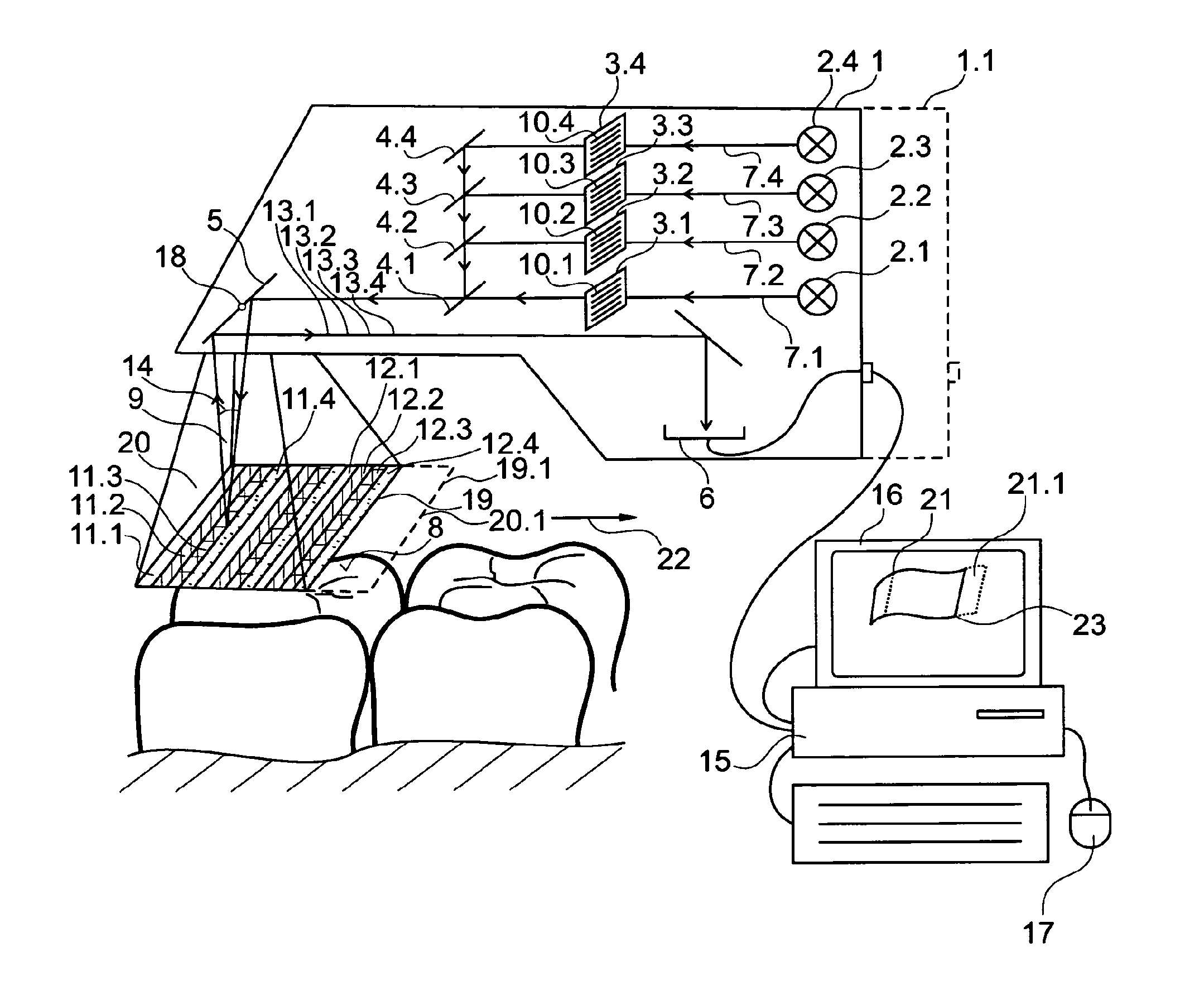
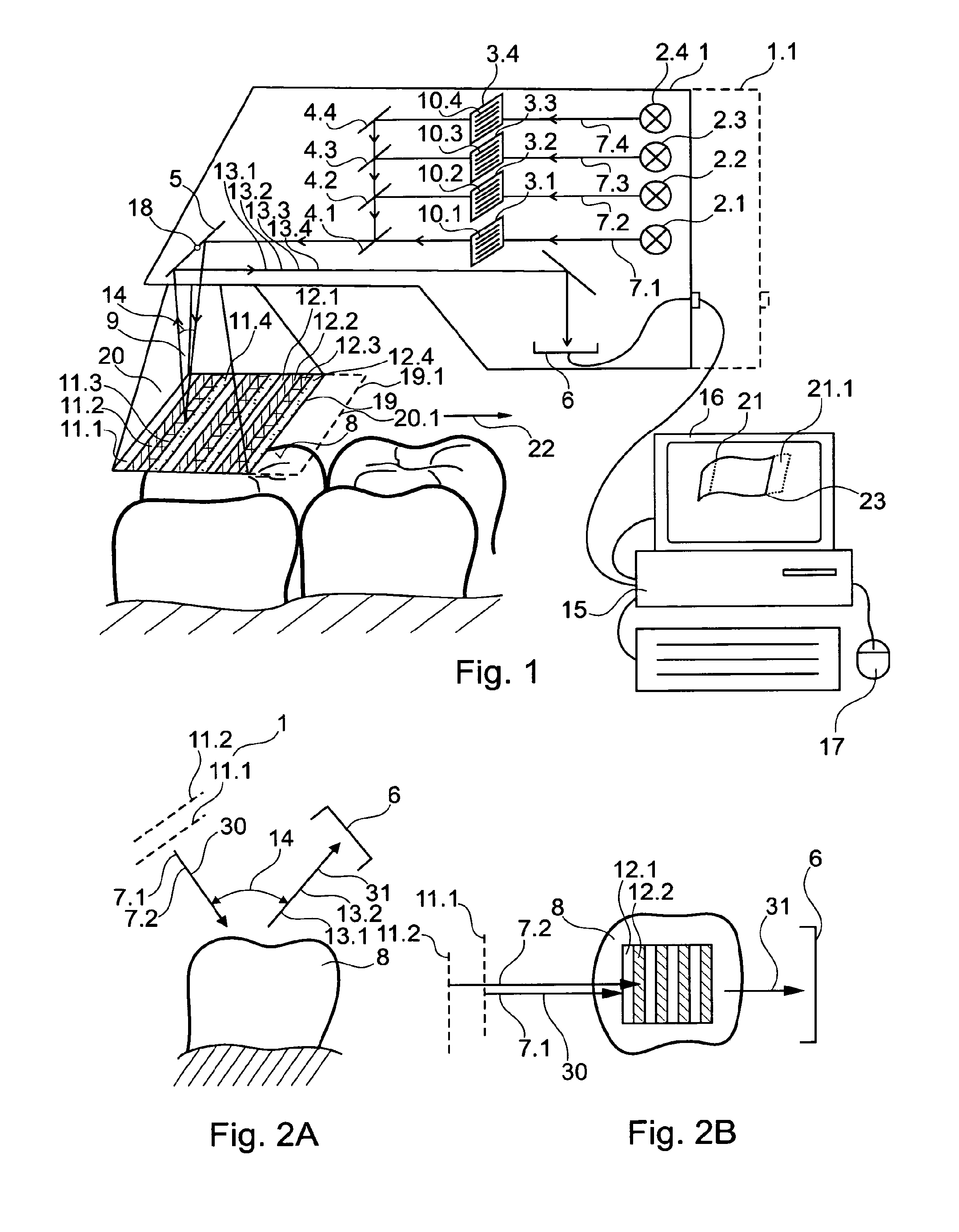
[0091]FIG. 1 is a sketch for illustration of the method of the invention. A dental intraoral camera is used as a recording apparatus 1, which dental intraoral camera comprises four light sources 2.1, 2.2, 2.3, 2.4, four diaphragm units 3.1, 3.2, 3.3, 3.4, four deflecting means 4.1, 4.2, 4.3, 4.4, a mirror 5 and a CCD sensor 6 as the recording units. The light sources 2.1, 2.2, 2.3, 2.4 emit projected beams 7.1, 7.2, 7.3, 7.4 that pass through the diaphragm units formed as grids 3.1, 3.2, 3.3, 3.4 and are deflected by the deflecting means 4.1, 4.2, 4.3, 4.4 to the mirror 5 and directed by the mirror 5 onto an object 8, namely the surface of a tooth. The deflecting means 4.2, 4.3, 4.4 completely deflect the projected beams 7.2, 7.3, 7.4, while the deflecting means 4.1 is semi-transparent and therefore allows the passage of the projection beam 7.1 therethrough and the partial deflection of the deflected projected beams 7.2, 7.3 and 7.4 to the mirror 5. The diaphragm units formed as opt...


PUM


Abstract

A method for optically measuring an object by means of an optical recording apparatus includes a triangulation method. A first shutter means is used to produce a first pattern and to project the first pattern as a first projection beam onto the object to be measured. At least one further shutter means is used to produce a further pattern and to project the further pattern as a further projection beam onto the object to be measured. The first pattern and the further pattern are passed back from the object as observation beams and are recorded by at least one recording means in order to obtain a three-dimensional data record of the object. The projected first pattern and the further pattern are recorded at the same time in at least one triangulation recording using the at least one recording means.

Description

CROSS REFERENCE TO RELATED APPLICATIONS[0001]The present application is a continuation of International Application No. PCT / EP2008 / 065627, filed Nov. 14, 2008, which claims priority to German Patent Application No. 10 2007 054 907.7, filed Nov. 15, 2007. The entire disclosure of each prior application is incorporated by reference herein.BACKGROUND OF THE INVENTION[0002]1. Field of the Invention[0003]The invention relates to a method for optical measurement of the three dimensional geometry of objects and is concerned with the task of 3D scanning when there is relative movement between the camera and the object when being scanned, particularly for dental purposes.[0004]2. Prior Art[0005]Digital design data for the computer-assisted production of dental prosthetic items without having to create the usual impression can be acquired by optically scanning one or more teeth in a patient's mouth.[0006]For such scanning, use is frequently made of measuring methods based on the principle of ...

Claims


Application Information

Patent Timeline
Patent Type & Authority Patents(United States)
IPC IPC(8): G06K9/00
CPCG01B11/2513G01B11/2518A61C9/004A61C13/0004A61C9/006
Inventor THIEL, FRANKPFEIFFER, JOACHIN
Owner SIRONA DENTAL SYSTEMS
Why Eureka
Try Eureka