Chain link

a chain link and chain technology, applied in the direction of hoisting chains, driving chains, hauling chains, etc., can solve the problems of heavy wear at the contact points, and achieve the effect of high impact resistance and high tensile strength

Active Publication Date: 2012-04-24
DE VRIES OSCAR
View PDF20 Cites 6 Cited by
  • Summary
  • Abstract
  • Description
  • Claims
  • Application Information

AI Technical Summary

Benefits of technology

[0010]It is an object of the invention to provide a light-weight link chain which overcomes these problems and combines high impact resistance and high tensile strength with traditional link shape so that existing facilities, in particular chain jacks and chain stoppers, can be used with it.
[0014]The end-portions—and optionally also the limbs—can be fitted with a recess along their outline in which the band of reinforcement fiber material is disposed. This way, the fiber material is effectively protected from impact and wear loads, and suffers less from impact fatigue.
[0016]It is possible to tit the inside contact areas of the end-portions with engineered surfaces, much like the way the human shoulder works. The end-portions would come in two varieties: male and female. The male variety has an extrusion, the female a recess. The male piece is able to rotate and slide in the female recess which reduces the wear normally seen between the contact areas of two chains. This way, the service life of the chain link can be extended.
[0020]In environments that are less extreme than offshore another embodiment of a chain link according to the present invention can be used. With this design, the end portions and limbs are surrounded by a sleeve of the fiber material. The end portions and limbs can for example be formed by a foam core comprising two mirrored shapes both forming half a side of a chain link. This foam can be polyurethane, although any material would be usable. The fibers can be embedded in a polymeric matrix, e.g. an epoxy or polyester matrix. Such a design can for example be attractive for the market of pleasure yachts and the like, where chains are generally subjected to much lower mechanical loads. The chains can be designed to be neutrally buoyant and could be marketed based on a fashionable and trendy outlook.
[0021]Such a chain link can be constructed by slipping a fiber sleeve over one of the mirrored shapes, then, the next shape would be placed next to the first one and the fiber would continue to be pulled or rolled from the first mirrored shape over the second mirrored shape. Preferably, the sleeve is somewhat longer than the perimeter of the core, so that the first end of the sleeve is slipped over its other end. This construction allows the chain to be made without any weak spots, since the fiber sleeve covers both the cores and essentially creates a one piece chain. The fiber sleeve can be made out of normal or pre-impregnated carbon fiber. However, pre-impregnated carbon fiber would have the advantage that the sleeve would not have to be treated with epoxies during application, thereby simplifying the construction process.

Problems solved by technology

In use these contact points are heavily subjected to wear.

Method used


Image

  • Chain link
  • Chain link
  • Chain link

Examples


Embodiment Construction

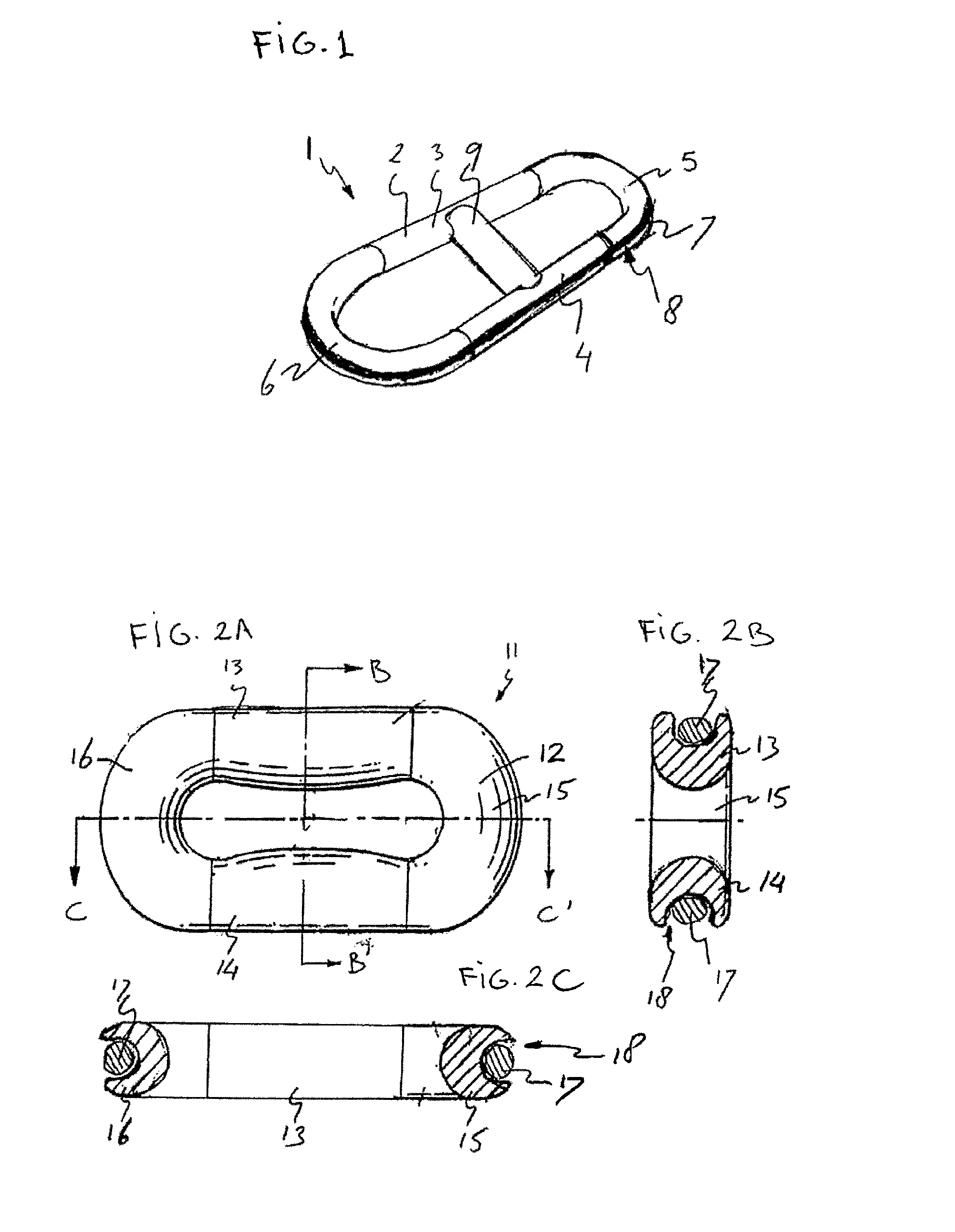
[0036]FIG. 1 shows a stud link 1 comprising a body 2 of two side limbs 3, 4 of a light weigh plastic material, such as polyurethane. At both ends the side limbs 3, 4 are mutually joined by curved steel end portions 5, 6. The end portions 5, 6 have the shape of a circular segment, the first end portion 5 being of a smaller curvature radius than the other end portion 6. The body 2 spans a band 7 of pre-tensioned unidirectional reinforcement fiber material, such as carbon fibers wound along the outer perimeter of the body 2. The end portions 5, 6 and the side limbs 3, 4 comprise a recess 8 extending along the outer perimeter of the body 2 to receive the band of reinforcement fiber material. A crossbar or stud 9 spaces the two limbs 3, 4. The crossbar 9 and the limbs 3, 4 are made of one single piece of a light weight plastic material, such as polyurethane foam. The end portions are made of steel.

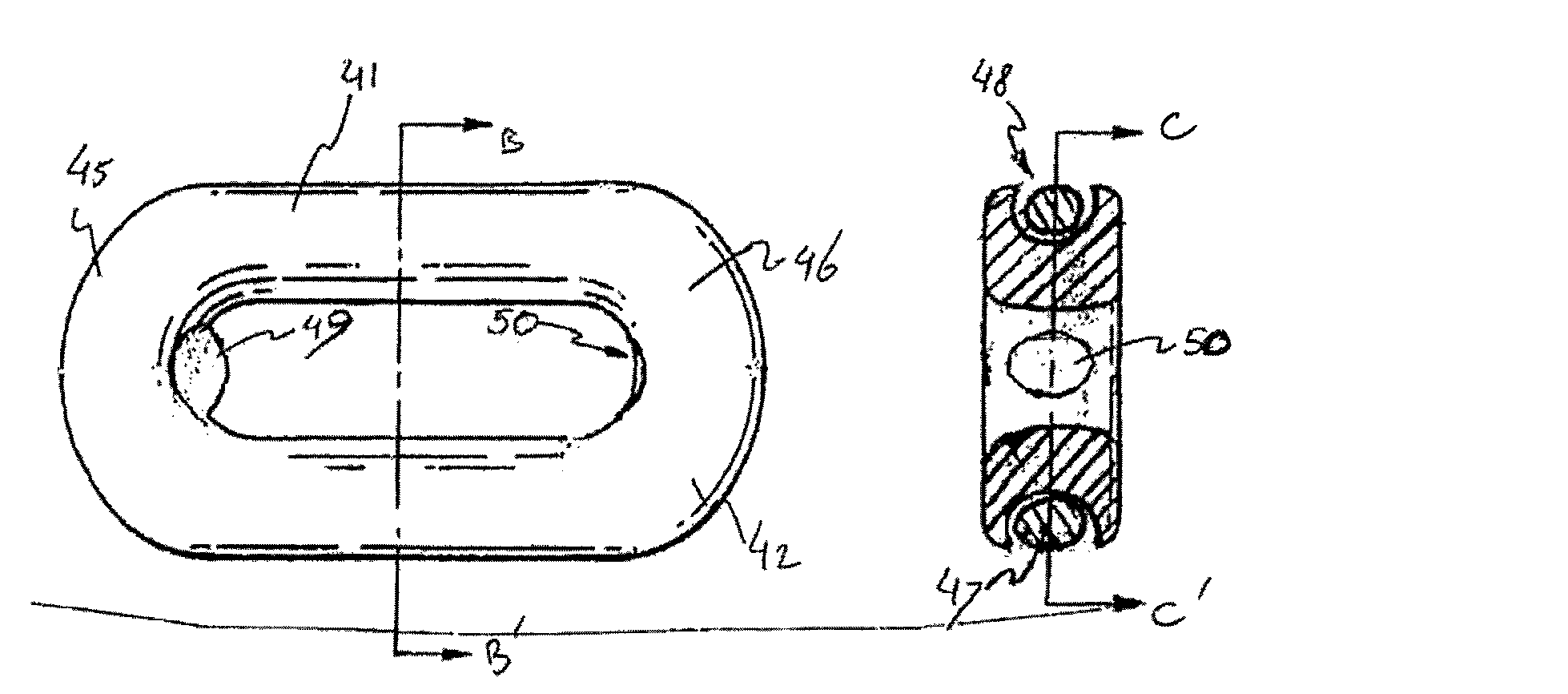
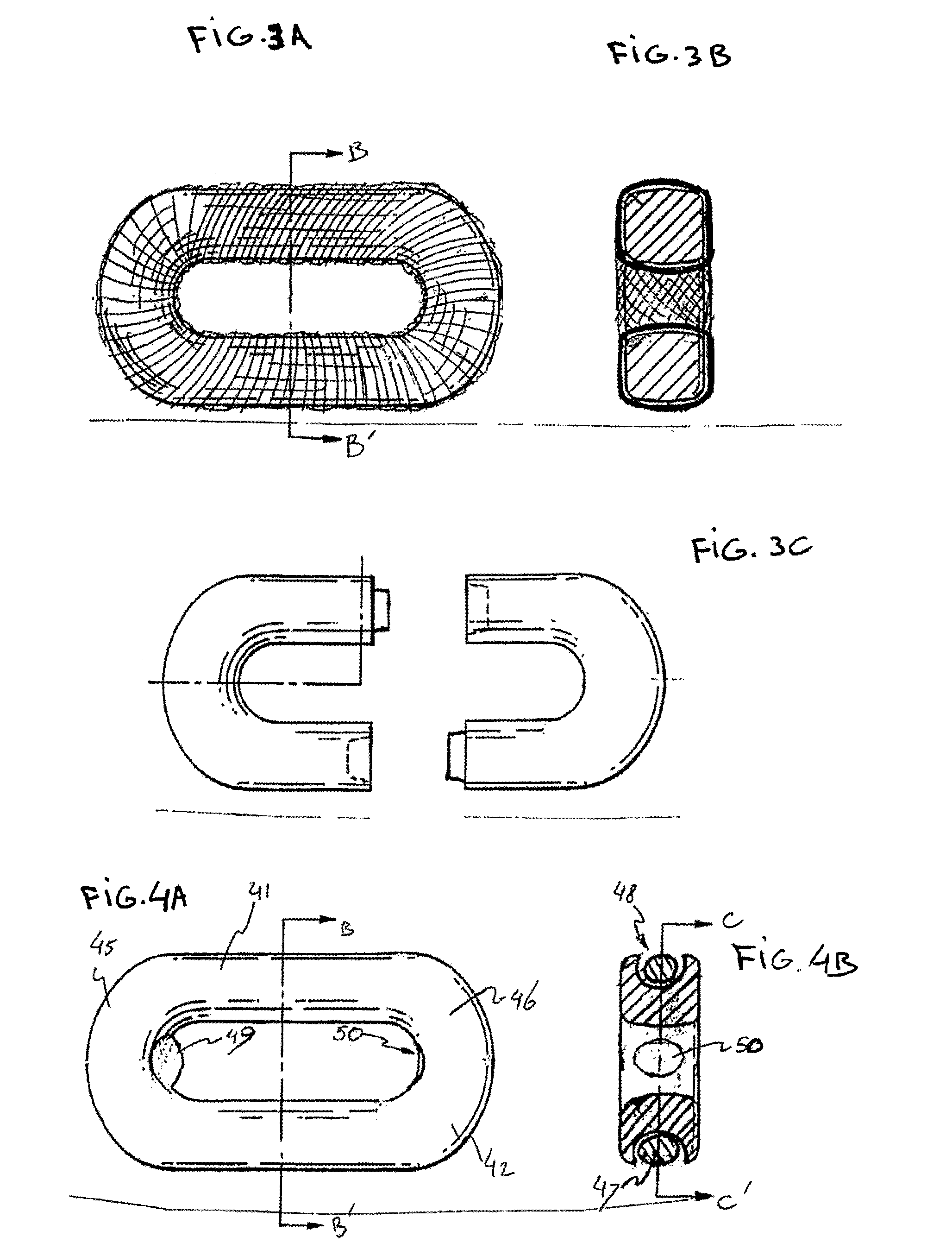
[0037]FIG. 2A shows a chain link 11 without a stud. The link 11 comprises a body 12 with si...


PUM

PropertyMeasurementUnit
cross sectional areaaaaaaaaaaa
perimeteraaaaaaaaaa
lengthaaaaaaaaaa

Abstract

Chain link comprising two side limbs at both ends joint by curved end portions. The chain Link comprises at least one endless band of fiber material wound along the perimeter of the chain link. The fiber material follows the longitudinal direction of the limbs and the curvature of the end-portions. In a chain made of interlocking chain links of this type, all tensile loads are absorbed by the fiber material, whereas the bearing load due to interlink contact, plus the link shear and bonding stresses near the contact points are absorbed by the end portions.

Description

CROSS-REFERENCE TO RELATED APPLICATIONS[0001]This application is the National Stage of International Application No. PCT / EP2008 / 061583, filed Sep. 2, 2008, which claims the benefit of European Application No. 07116747.2, filed Sep. 19, 2007, the contents of which is incorporated by reference herein.FIELD OF THE INVENTION[0002]The invention relates to a chain link and a chain, e.g. long, high strength chains of interlocking chain links for mooring lines and tension legs used to connect, offshore platforms or other buoyant marine constructions to the sea floor or anchor chains for yachts or other ships.BACKGROUND OF THE INVENTION[0003]Mooring lines and tension legs are generally made from steel link chain cables or polyester ropes having a cross sectional area of up to 750 cm2. In service they carry tensile loads for long periods while submerged in sea water. The weight of steel in sea water is 92 percent of its weight in air. Therefore, due to the weight of the steel chains, the buoy...

Claims


Application Information

Patent Timeline
Patent Type & Authority Patents(United States)
IPC IPC(8): F16G13/12F16G15/12
CPCF16G13/12F16G13/14F16G15/02
Inventor DE VRIES, OSCAR
Owner DE VRIES OSCAR
Why Eureka
Try Eureka