
Multi-group transmission and method for changing gear in a multi-group transmission

a multi-group transmission and gear change technology, applied in fluid gearings, gearings, transportation and packaging, etc., can solve the problems of slowing affecting the driving speed of the vehicle, and not shifting under load, so as to increase the driving torque of the vehicle

Active Publication Date: 2012-04-24
ZF FRIEDRICHSHAFEN AG
View PDF9 Cites 10 Cited by
  • Summary
  • Abstract
  • Description
  • Claims
  • Application Information

AI Technical Summary

Benefits of technology

[0017]The design of a multi-group transmission with an input transmission and a main transmission makes a direct connection possible, between an input shaft and a main shaft, via the load shifting mechanisms in order to reduce the speed of the drive engine via the startup element, that is, a startup clutch, and thereby utilize the dynamic torque of the drive engine to shift to an intermediate gear, while the jaw clutches and synchronizations of the two transmission groups are shifted to their neutral position during gear change.
[0018]Advantageously achieved by way of this intermediate gearshifting is that the vehicle makes available a tractive force support during a shifting operation which is desired and allowed by the driver and which makes driving in the desired target gear possible after the shifting operation has ended and also reliably prevents, in particular, an immediate shift-in, due to a speed reduction caused by the tractive force interruption during gear change.
[0020]A disk clutch can be provided as particularly effective and simple load shifting mechanisms. The latter is arranged between the first transmission group and the second transmission group in the simplest case. The load shifting mechanisms or disk clutch can likewise be provided between the startup element and the first transmission group. This is made possible by way of a main shaft, which is axially guided through the input transmission and is connected to an inner clutch part of the disk clutch, so that the disk clutch is arranged between the startup clutch and the transmission input and is also connected via an outer clutch part to the input shaft and the input transmission. The axial preference of the disk clutch makes an especially compact design possible, in particular, in a two-speed or three-speed main transmission.
[0023]A further objective of the invention is the disclosure of a process for gear change with a multi-group transmission with which gear changes are made possible with high operational comfort and, for the most part, free of tractive force interruptions.

Problems solved by technology

A fundamental disadvantage of this automated standard transmission in comparison to other automatic transmissions is, however, that it does not shift under load, but is subject to an interruption of tractive force during gear changes when shifting the usual shift elements (jaw clutches, synchronizing devices).
This can slow the driving speed of the vehicle, depending on the driving situation, in particular with regard to heavy trucks, in such a way that a shift-in takes place immediately after a shifting operation has ended.
A standstill can even occur in an extreme case, when driving uphill with heavy load or starting on an uphill.
It is thereby disadvantageous that the known multi-group transmission has the tractive force interruption known from the standard transmissions, which can lead to the above-described problems during gear changes and high comfort loss during driving operation, especially in utility vehicles.
It is considered disadvantageous that the operation of the startup clutch at the slip limit is subjected to relatively intensive wear due to the frequent gearshifting.
In addition, the known process for gear change in single group transmissions is not suitable by implication for multi-group transmissions, which have one input shaft and at least one further main shaft.

Method used


Image

  • Multi-group transmission and method for changing gear in a multi-group transmission
  • Multi-group transmission and method for changing gear in a multi-group transmission
  • Multi-group transmission and method for changing gear in a multi-group transmission

Examples


Embodiment Construction

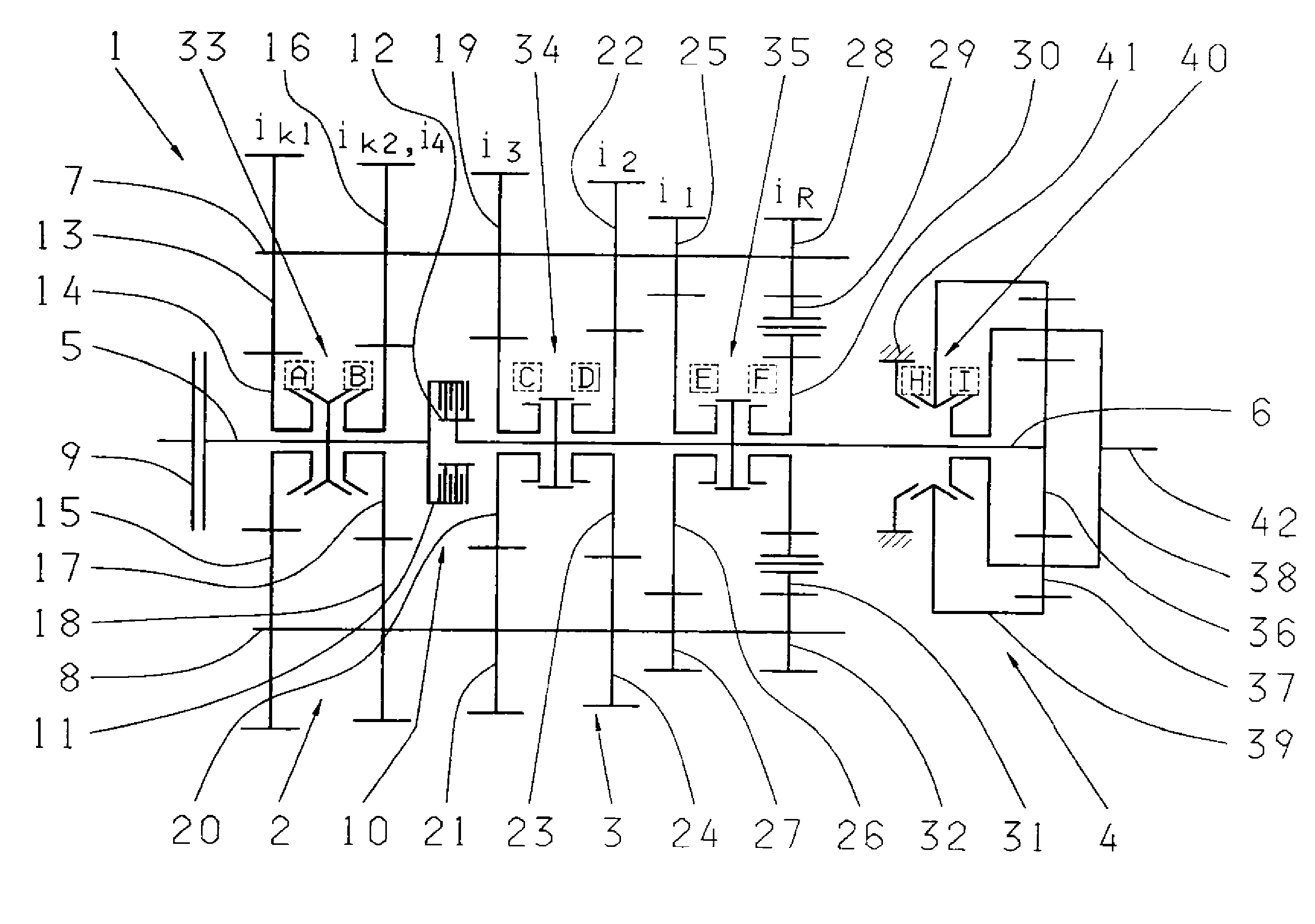
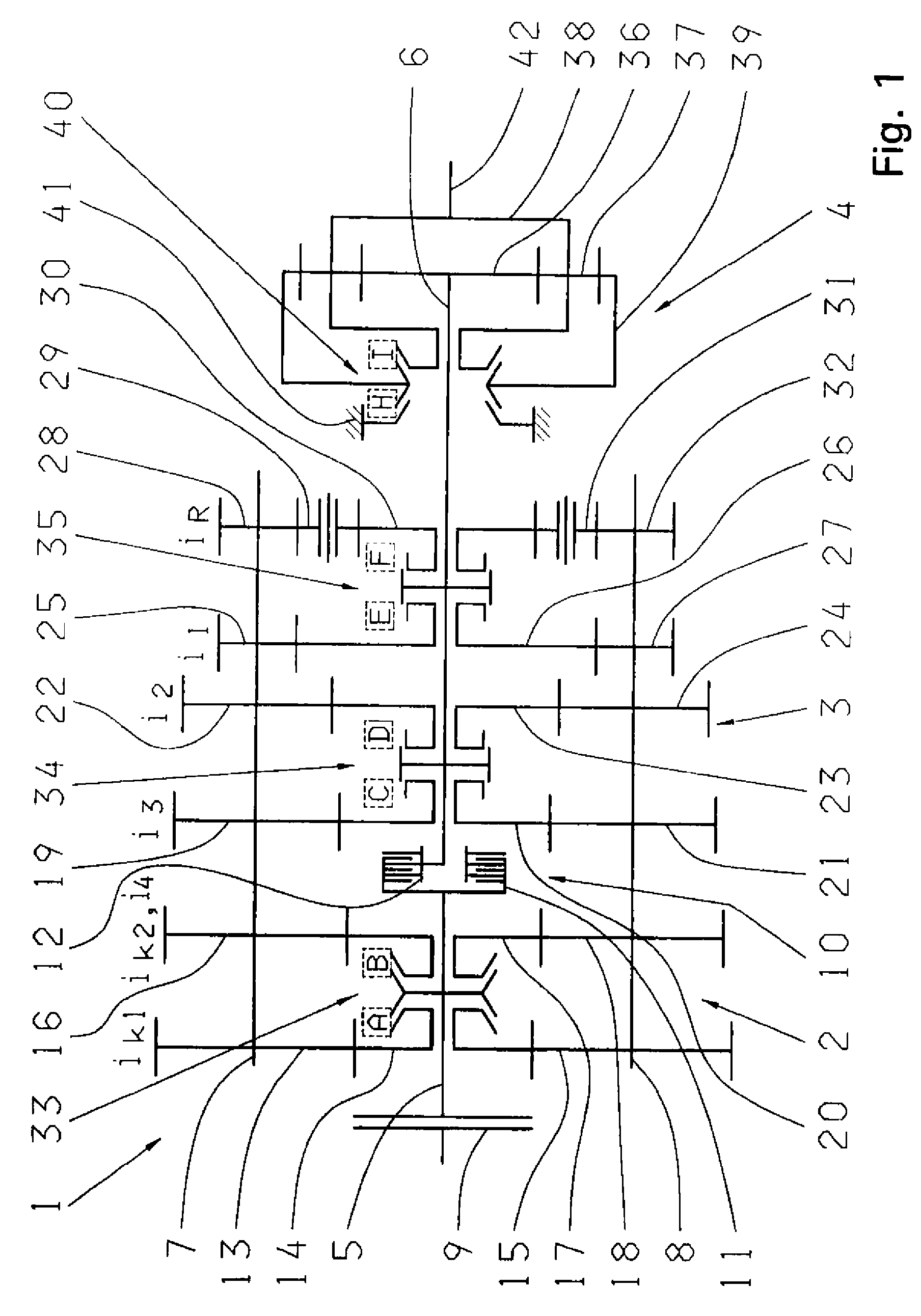
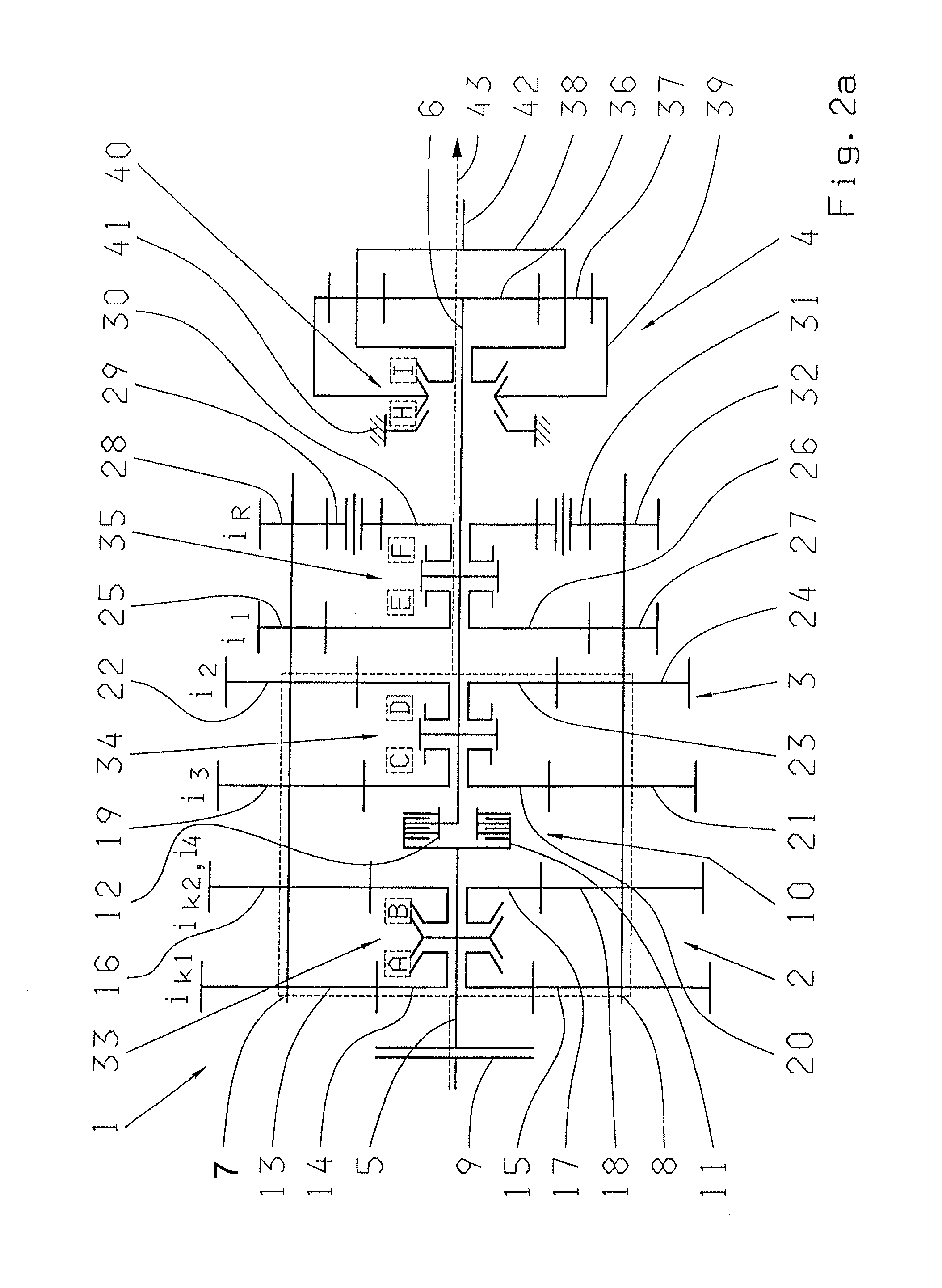
[0038]A multi-group transmission, which is configured as an automated two-countershaft transmission 1 of a utility vehicle having three transmission groups 2, 3 and 4 is accordingly represented in FIG. 1. A transmission controller (not depicted here) is provided for functional control. A transmission such as this and its mode of operation—without intermediate gearshift—are known to experts from the ZF-ASTRONIC series of the Applicant. The transmission shown here is configured as a 16-gear version, whereby the 16th gear is engaged as a direct gear.

[0039]A startup element 9, preferably configured as an engine clutch, is arranged on the input side on an input shaft 5 of the transmission 1. A drive engine (not shown) of the vehicle can be connected to the transmission 1 via the startup clutch 9. The input shaft 5 leads into the first transmission group 2, which is configured as a two-speed power split transmission. A main shaft 6 guided through the second transmission group 3, which is ...


PUM


Abstract

An automated multi-group standard transmission, for a utility vehicle, and a process for changing gears in the multi-group transmission. The multi-group transmission includes at least two multi-speed transmission groups arranged one after the other, such that a multitude of gears can be shifted. A transmission input shaft that can be connected to an engine, via a startup element, is associated with a first transmission group and a second transmission main shaft is associated with a second transmission group. Load shifting mechanisms produce a temporary direct connection between the transmission input shaft and the transmission main shaft such that an intermediate gear can be shifted during a gear change from an original gear into a target gear. The load shifting mechanism enables gear changes that are virtually free of interruptions in load transfer during a gear change from a lower to a higher gear, thus increasing a high operational comfort.

Description

[0001]This application is a national stage completion of PCT / EP2007 / 054039 Apr. 25, 2007, filed which claims priority from German Application Serial No. 10 2006 024 370.6 filed May 24, 2006.FIELD OF THE INVENTION[0002]The invention concerns a multi-group transmission and a method for changing gears in a multi-group transmission.BACKGROUND OF THE INVENTION[0003]Multi-group transmissions are used as multi-speed transmissions mainly in utility vehicles. They consist of a power split transmission as a transfer case or input transmission, a main transmission as the basic transmission and a range transmission as a rear-mounted transmission. These transmissions are increasingly more frequently configured as automated standard transmissions, such as the Applicant's known ASTRONIC transmission system typically make available a number of 8, 10, 12 or 16 gears. They offer more operating comfort in comparison with conventional manual transmissions, in particular an easier and almost force-free ...

Claims


Application Information

Patent Timeline
Patent Type & Authority Patents(United States)
IPC IPC(8): F16H3/08F16H47/00
CPCF16H37/043F16H37/046F16H61/702F16H61/0403F16H2061/0425F16H2200/003F16H2061/0429Y10T74/19167Y10T74/19233Y10T74/19321F16H3/02F16H37/04F16H61/70F16H61/04
Inventor BORNTRAGER, KAI
Owner ZF FRIEDRICHSHAFEN AG
Learn More