Apparatus for cutting food product

a technology for food products and cutting tools, applied in the direction of metal working tools, etc., can solve the problems of starch loss, reduced cutting edge precision, and difficulty in producing slices with consistent thicknesses, so as to reduce product compression, improve cutting accuracy, and improve cutting efficiency

Active Publication Date: 2012-04-24
URSCHEL LAB +1
View PDF12 Cites 62 Cited by
  • Summary
  • Abstract
  • Description
  • Claims
  • Application Information

AI Technical Summary

Benefits of technology

[0009]According to one aspect of the invention, the knife is clamped to the cutting head with a clamping feature that includes a clamping bar with which the clamping feature generates a clamping force to secures the knife to the cutting head. The clamping bar is located adjacent a radially outermost extremity of the knife, oriented substantially parallel to the knife, and has a thickness in a radial direction of the cutting head that decreases in a direction toward the knife to provide clearance for the slices when traveling the trajectory plane of the knife. A significant advantage of this aspect of the invention is that slices of food product can be ejected from the cutting head without striking any structure downstream, and without resorting to the use of a double-beveled knife or sheathing the knife in a plastic cartridge. As such, the knife can have a single-bevel cutting edge to minimize compression of the product, and the cutting edge of the knife can be located with greater precision to produce slices with more consistent thicknesses.
[0010]The impeller assembly is preferably equipped with paddles to deliver the food products radially outward toward the cutting head. According to another aspect of the invention, each paddle has a radially outer extremity adjacent a periphery of the impeller assembly, an oppositely-disposed radially inner extremity, and a face between the radially inner and outer extremities and facing the rotational direction of the impeller assembly. Each paddle has grooves parallel to the radially outer extremity thereof. According to yet another aspect of the invention, each paddle has a plurality of removable posts mounted to its radially outer extremity and extending in a radially outward direction of the impeller assembly. A significant advantage achieved with the grooved paddles is to discourage smaller food products from rolling within the impeller. A significant advantage achieved with the removable posts is to avoid stones and other contaminants mixed with the product from being forced into and damaging the knife cutting edge.

Problems solved by technology

In the case of slices cut from potatoes and cooked in oil to produce potato chips, compression during slicing can be sufficient to cause starch loss, which undesirably promotes oil absorption during cooking.
Though the plastic cartridge 30 avoids this by deflecting slices away from the clamping rod 32, the compressibility of the plastic material reduces the precision with which the cutting edges 15 of the knives 14 can be located, making production of slices with consistent thicknesses difficult.
Other variables that can affect the operation of the Model CC® slicing machine and / or reduce the consistency of slices include the presence of contaminants such as stones embedded or mixed in with the products, which can damage the cutting edges of the knives, and the use of small products that tend to roll within the impeller 10.

Method used


Image

  • Apparatus for cutting food product
  • Apparatus for cutting food product
  • Apparatus for cutting food product

Examples


Embodiment Construction

[0024]FIGS. 4A, 4B, and 4C show a modified impeller assembly 40 in accordance with the present invention. As depicted in FIG. 5, the impeller assembly 40 is configured for rotation within cutting heads similar to the cutting head 12 of FIG. 3, as well as cutting heads 42 configured in accordance with FIGS. 11 through 13.

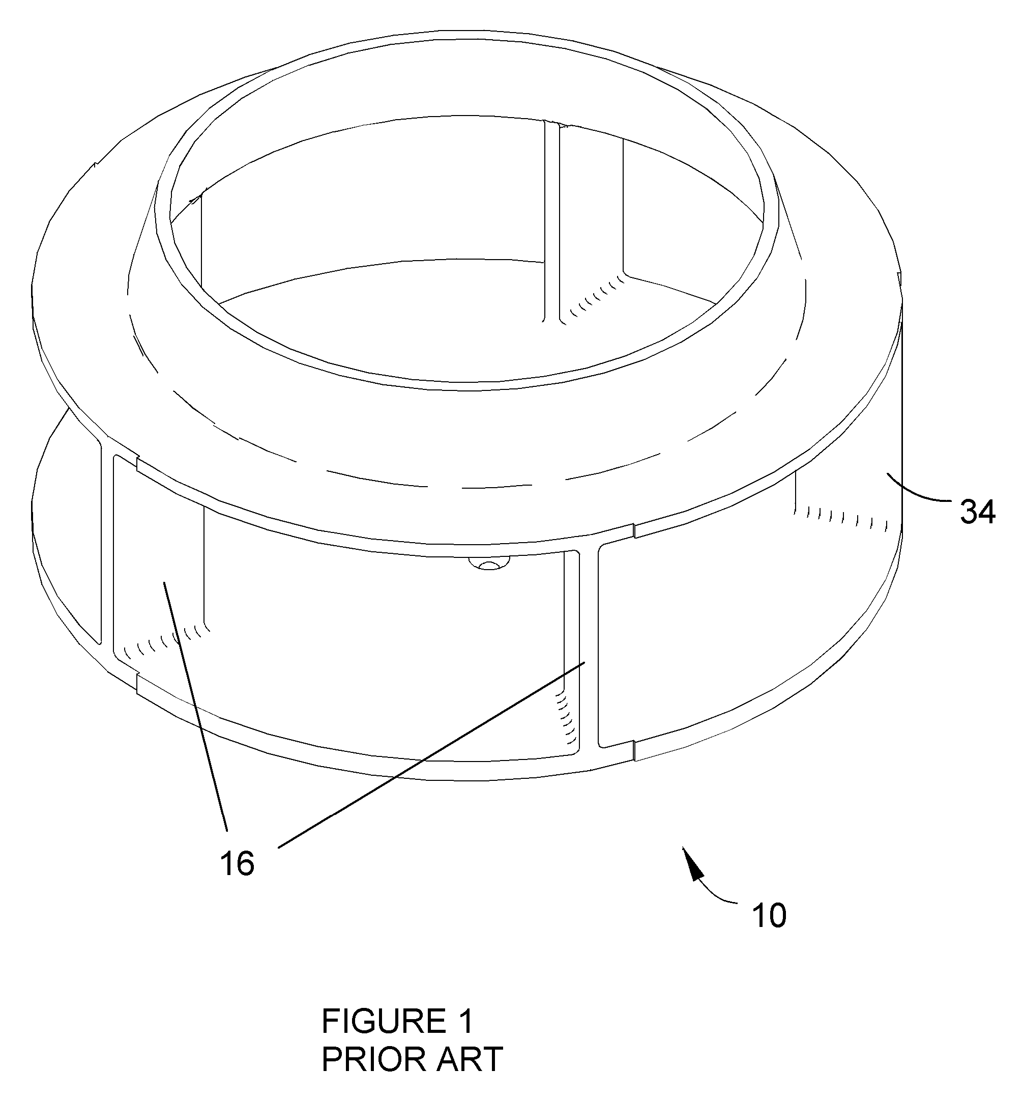
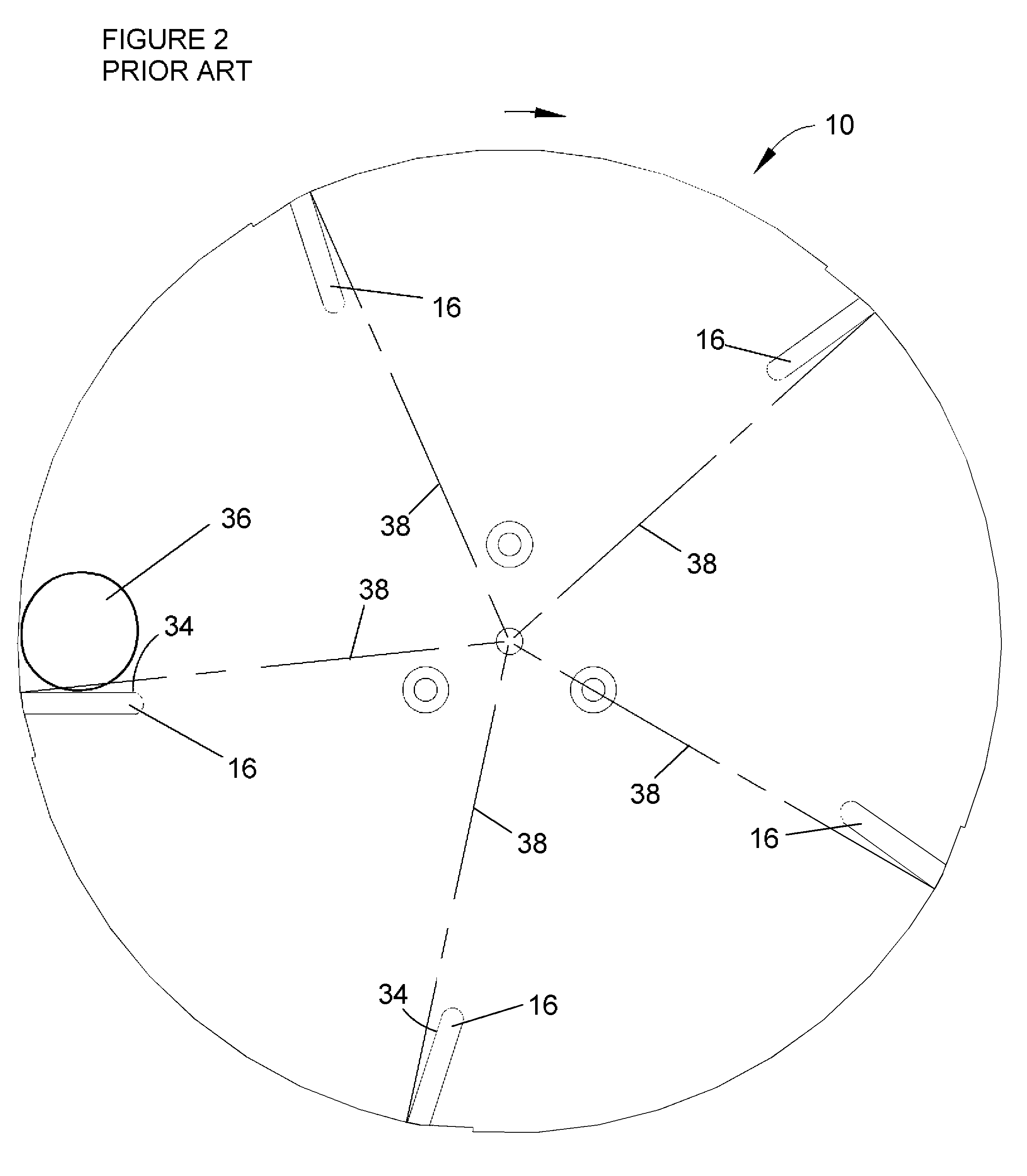
[0025]Similar to the impeller 10 of FIGS. 1 and 2, the impeller assembly 40 has generally radially-oriented paddles 46 with faces 60 that engage and direct food products (e.g., potatoes) radially outward against knives of the cutting head as the impeller assembly 40 rotates. However, as evident from FIGS. 4A, 4B, and 4C, the paddles 46 are significantly different in construction and configuration from the prior art paddles 16 of FIGS. 1 and 2. Because of the configuration of the paddles 46, the impeller assembly 40 is preferably constructed of individually formed paddles 46 mounted and secured between a pair of annular-shaped plates 48 and 50. As a result of its modu...


PUM

PropertyMeasurementUnit
diametersaaaaaaaaaa
diametersaaaaaaaaaa
diametersaaaaaaaaaa

Abstract

A cutting apparatus having an annular-shaped cutting head and an impeller assembly coaxially mounted for rotation within the cutting head to deliver food products radially outward toward the cutting head. The cutting head has at least one knife extending radially inward toward the impeller assembly. The knife has a cutting edge at a radially innermost extremity and a radially outer face that defines a trajectory plane for slices removed from the products by the cutting edge. The knife is clamped to the cutting head with a clamping feature that provides clearance for slices when traveling the trajectory plane of the knife.

Description

CROSS REFERENCE TO RELATED APPLICATIONS[0001]This application claims the benefit of U.S. Provisional Application No. 60 / 745,028, filed Apr. 18, 2006, the contents of which are incorporated herein by reference.BACKGROUND OF THE INVENTION[0002]The present invention generally relates to cutting methods and equipment. More particularly, this invention relates to an apparatus equipped with an impeller assembly that positions and orients elongate food products prior to encountering a cutting device that produces size-reduced products of generally consistent thickness.[0003]Various types of equipment are known for slicing, shredding and granulating food products such as vegetables, fruits, and meat products. A particular example is slicing equipment adapted for cutting root vegetables such as potatoes into thin slices suitable for making potato chips (also known as potato crisps). A widely used machine for this purpose is commercially available from Urschel Laboratories, Inc., under the na...

Claims


Application Information

Patent Timeline
Patent Type & Authority Patents(United States)
IPC IPC(8): B26D1/03
CPCB26D1/03B26D7/0691B26D7/2614B26D1/36B26D7/06Y10S83/932Y10T83/6473B26D2001/0053
Inventor JACKO, MICHAEL S.KING, DANIEL WADEBAJEMA, RICK WENDELLJONES, ANNETTE STIERSWARREN, DAVID RAY
Owner URSCHEL LAB
Why Eureka
Try Eureka