
Internal combustion engine

a technology of internal combustion engine and blowby gas, which is applied in the direction of combustion engine, lubrication of auxiliaries, casings, etc., to achieve the effect of reducing the loss of pumping of the internal combustion engin

Active Publication Date: 2012-04-24
NISSAN MOTOR CO LTD
View PDF10 Cites 4 Cited by
  • Summary
  • Abstract
  • Description
  • Claims
  • Application Information

AI Technical Summary

Benefits of technology

The patent text describes a device that processes blow-by gas in an internal combustion engine. The device includes an oil separator that separates oil from the blow-by gas. The device also includes a gas introducing chamber that allows gas to flow between the crank chambers. The device is designed to improve the separation of oil from the blow-by gas and reduce pumping loss in the engine. However, the prior art device may have a problem with the oil separation efficiency when trying to improve it. The invention provides a solution by adding a guiding mechanism that directs the blow-by gas from a specific hole to the oil separator in a way that reduces the impact of differences in flow path distances between the crank chambers and the oil separator. The technical effect of this invention is to increase the oil separation efficiency of the oil separator without impairing the pumping loss reduction effect of the gas-introducing chamber.

Problems solved by technology

In the blow-by gas-processing device according to the prior art, however, a problem may arise when attempting to improve the oil component separation efficiency of the oil separator.

Method used


Image

  • Internal combustion engine
  • Internal combustion engine
  • Internal combustion engine

Examples


Embodiment Construction

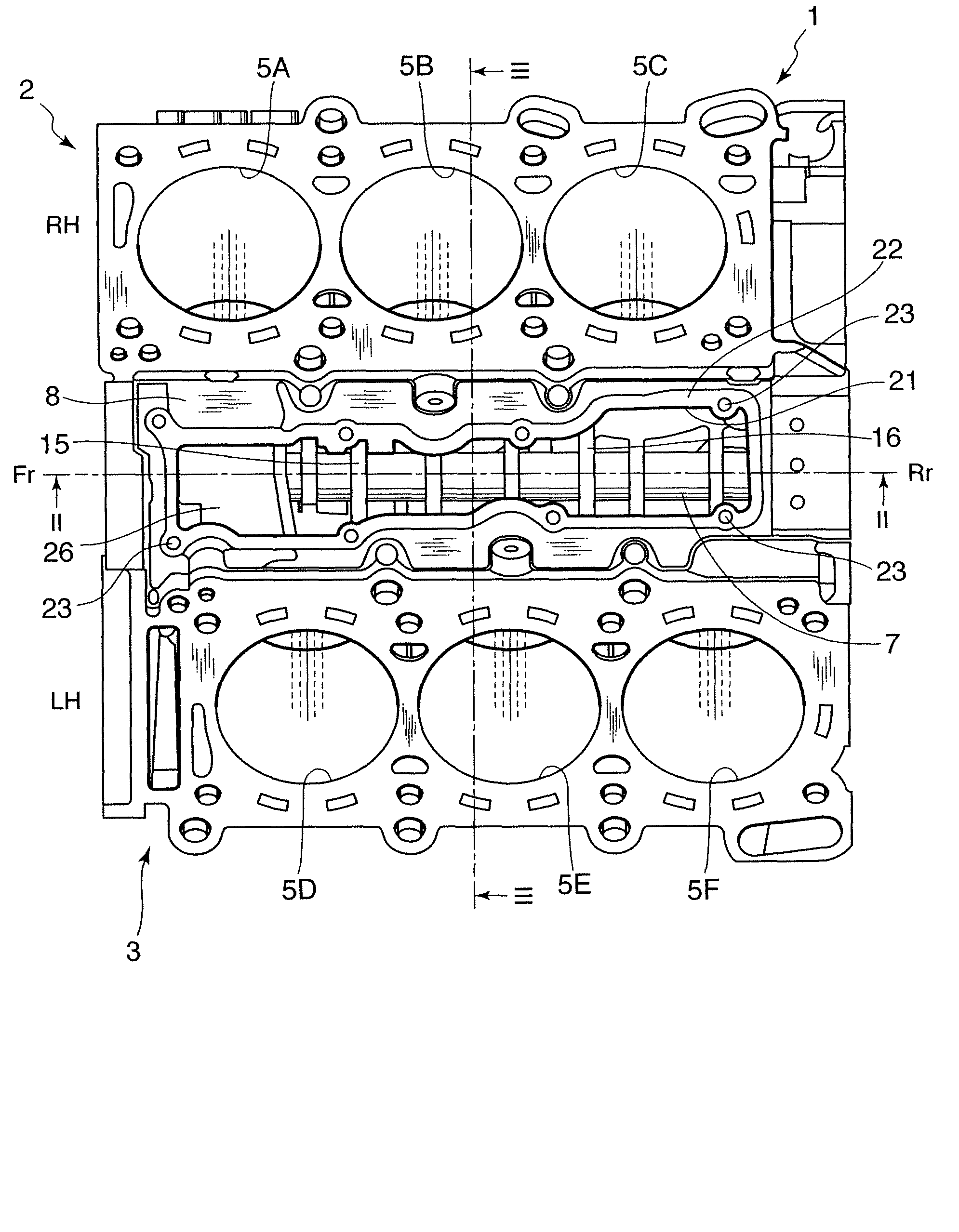
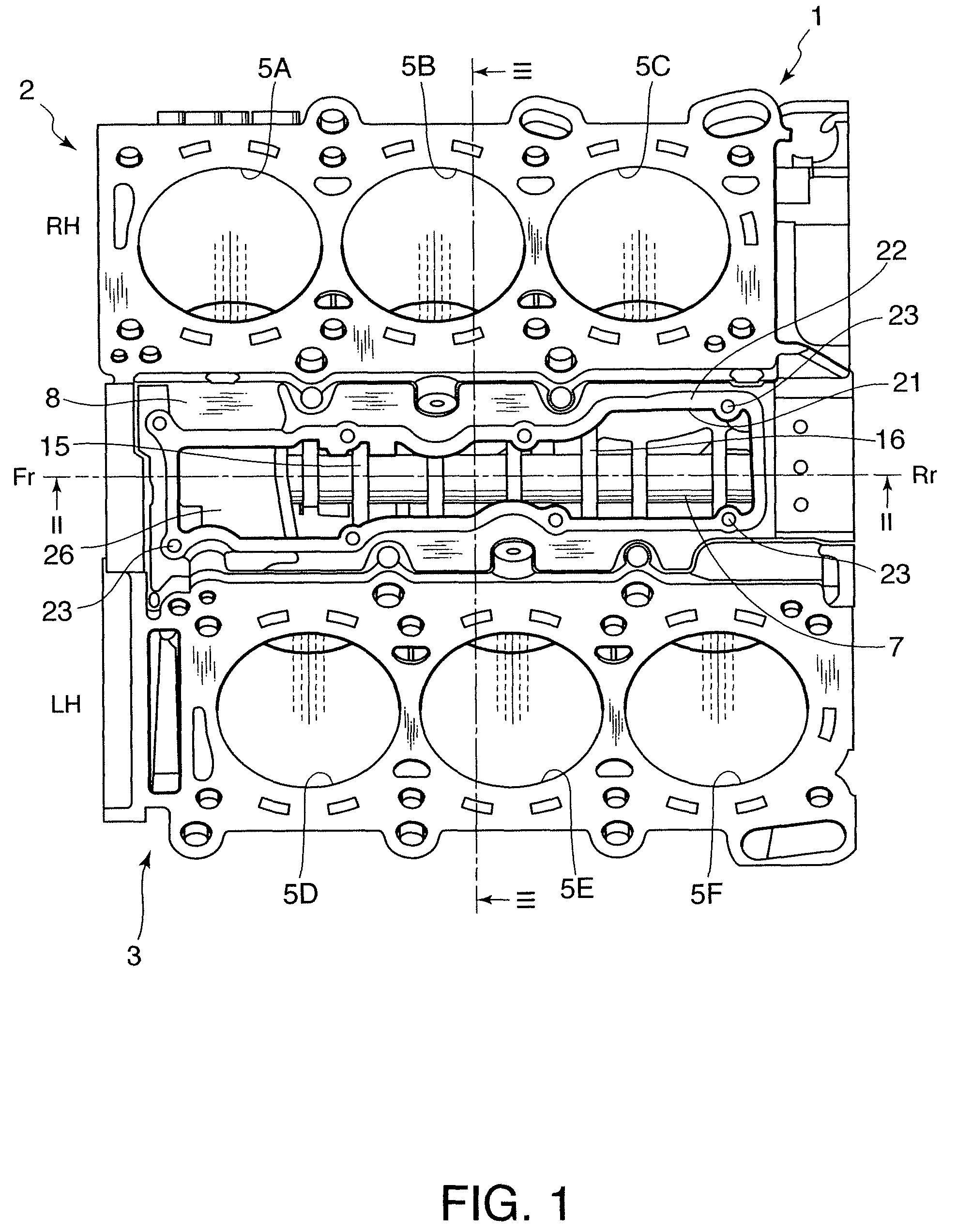
[0020]Referring to FIG. 1 of the drawings, a cylinder block 1 of a six-cylinder a V-shaped internal combustion engine comprises a right cylinder bank 2 which encloses three cylinders 5A, 5B, and 5C, and a left cylinder bank 3 which encloses three cylinders 5D, 5E, and 5F. Fr in the figure denotes an engine front and Rr in the figure denotes an engine rear. Accordingly, in each cylinder bank, the cylinders are aligned in a row in the front-aft direction of the internal combustion engine. The cylinders 5A, 5B, and 5C in the right cylinder bank 2 are shifted slightly towards the engine front with respect to the cylinders 5D, 5E, and 5F in the left cylinder bank 3.

[0021]Referring to FIG. 3, a water jacket 6A is formed in the right cylinder bank 2 on the inner side of the cylinders 5A, 5B, and 5C. A water jacket 6B is formed in the left cylinder bank 3 on the inner side of the cylinders 5D, 5E, and 5F.

[0022]A piston is enclosed in each of the six cylinders 5A-5F and caused to slide there...


PUM


Abstract

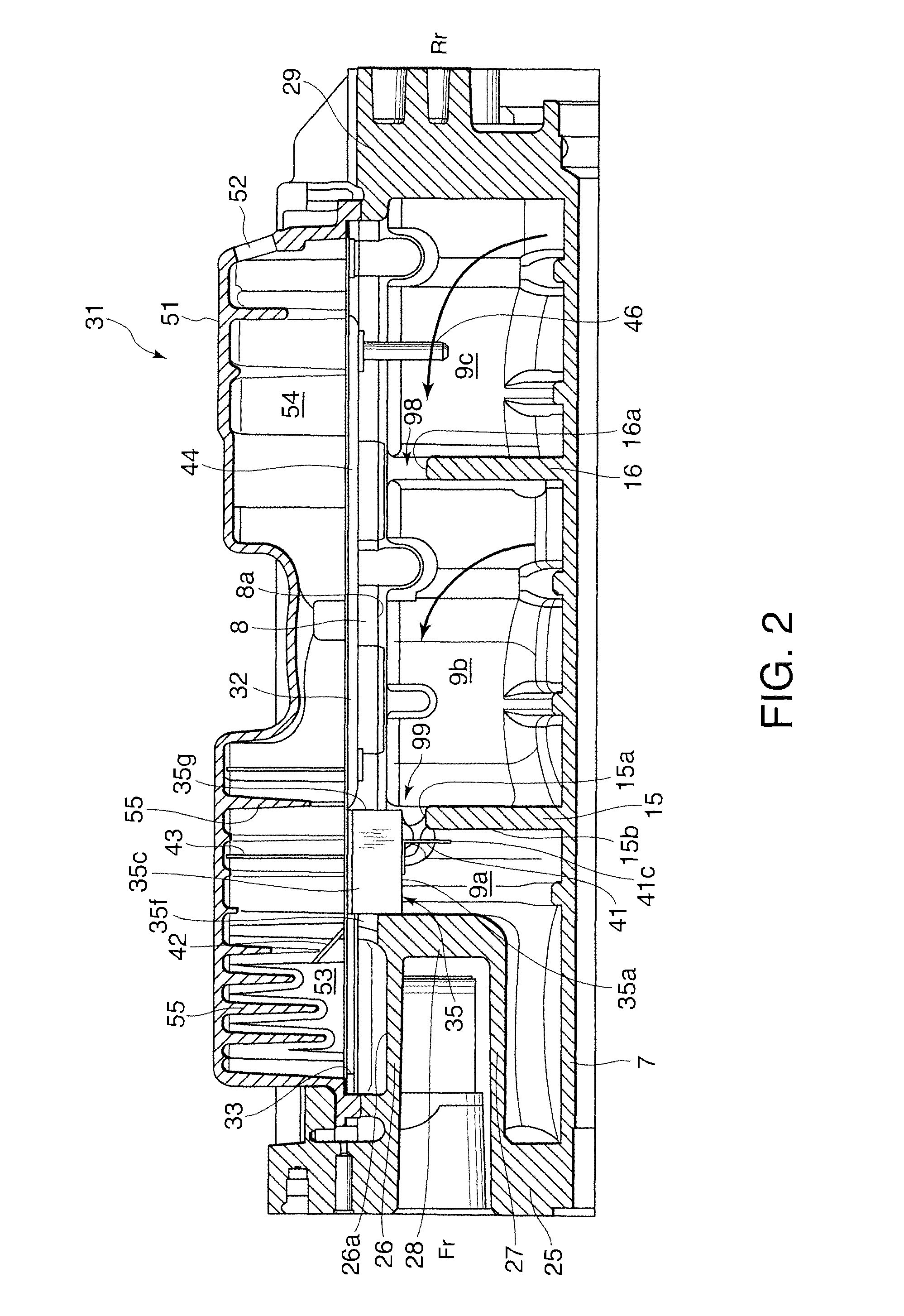
Blow-by gas in a plurality of crank chambers (71-73) in a V-shaped internal combustion engine is led to a plurality of gas introducing chambers (9a, 9b, 9c) via communicating holes (11-14). The blow-by gas then flows into an oil separator (31), which extends in a front-aft direction of the internal combustion engine, from the gas introducing chambers (9a, 9b, 9c). The blow-by gas inlet (33) of the oil separator (31) is provided in the vicinity of the engine front or the engine rear. By providing a guide member (35, 41) which guides the blow-by gas from the gas introducing chamber (9a) which is closest to the blow-by gas inlet (33) to the blow-by gas inlet (33) in a direction heading away from the blow-by gas inlet (33) and then guides it to the blow-by gas inlet (33), pumping loss in the internal combustion engine can be reduced.

Description

FIELD OF THE INVENTION[0001]This invention relates to the processing of blow-by gas generated in an internal combustion engine.BACKGROUND OF THE INVENTION[0002]JPS62-085110A, published by the Japan Patent Office in 1987, discloses a blow-by gas processing device which collects blow-by gas blown out from cylinders to corresponding crank chambers of a V-shaped internal combustion engine in a gas introducing chamber which is disposed above the crank chambers and applies an oil separation process in an oil separator disposed above the gas introducing chamber. After separating an oil component in the oil separator, the blow-by gas is recirculated into an intake passage of the V-shaped internal combustion engine.[0003]The gas-introducing chamber is formed in a space between a pair of cylinder banks of the V-shaped internal combustion engine. The V-shaped internal combustion engine comprises a plurality of crank chambers which are connected to the gas-introducing chamber via communicating ...

Claims


Application Information

Patent Timeline
Patent Type & Authority Patents(United States)
IPC IPC(8): F02B25/06
CPCF01M13/02F01M13/04
Inventor MOCHIDA, HIROAKI
Owner NISSAN MOTOR CO LTD
Learn More