
Warming Intake Air Using EGR Cooler in Dual-Throttle Boosted Engine System

a dual-throttle, boosted engine technology, applied in the direction of electric control, combustion air/fuel air treatment, instruments, etc., can solve the problems of increasing the ageing of materials in the engine system, reducing the temperature of combustion and exhaust, and transient control difficulties in the boosted engine system, so as to improve the transient control in the egr equipped engine system, and reduce the cost of boosting the engin

Active Publication Date: 2011-06-09
FORD GLOBAL TECH LLC
View PDF26 Cites 24 Cited by
  • Summary
  • Abstract
  • Description
  • Claims
  • Application Information

AI Technical Summary

Benefits of technology

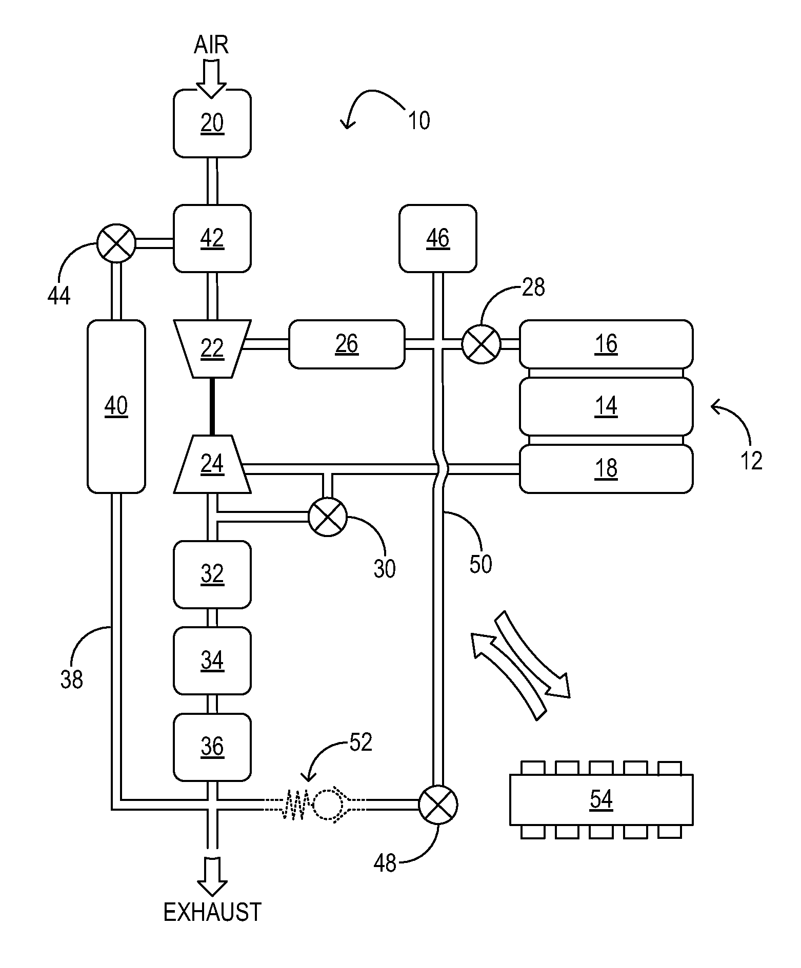
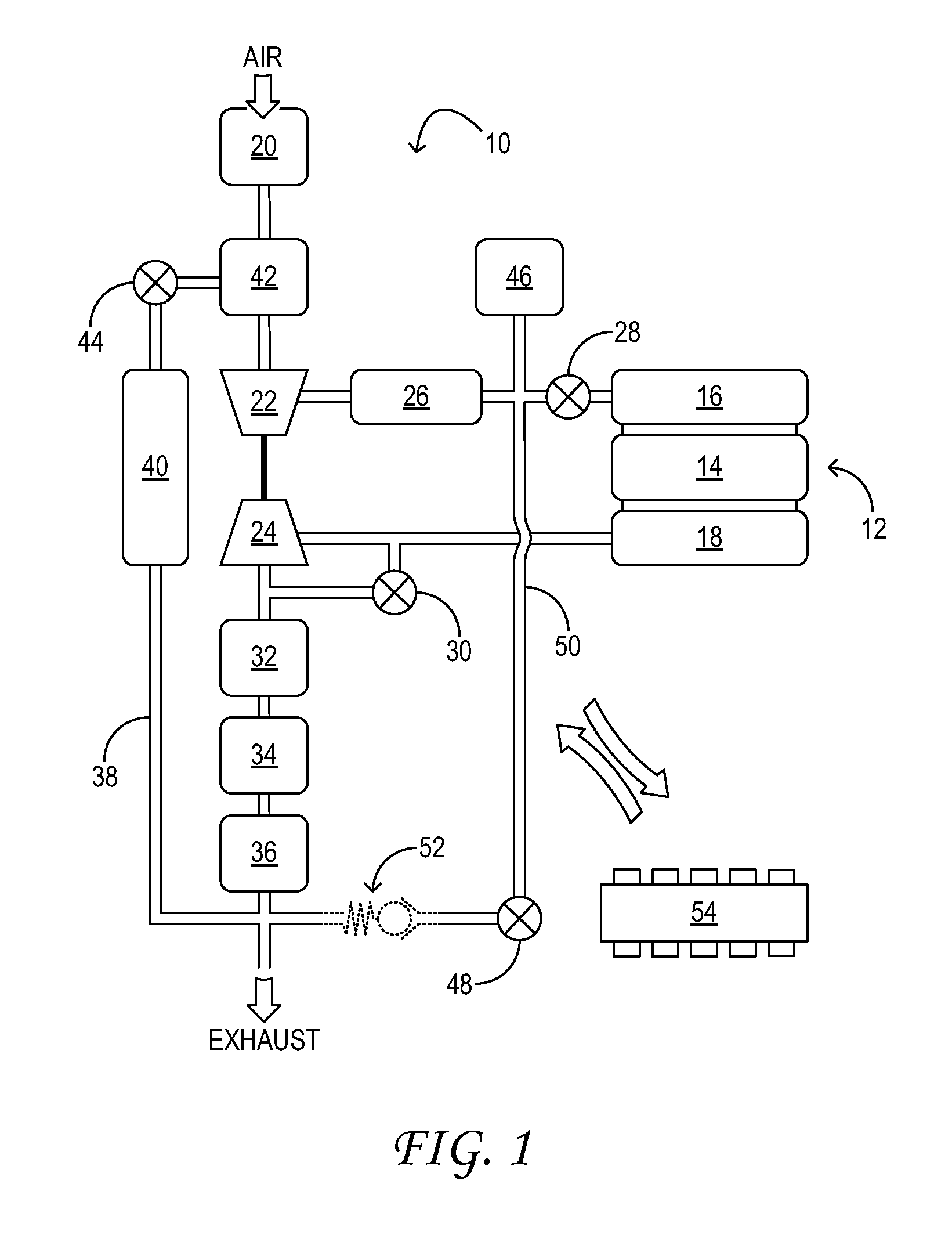
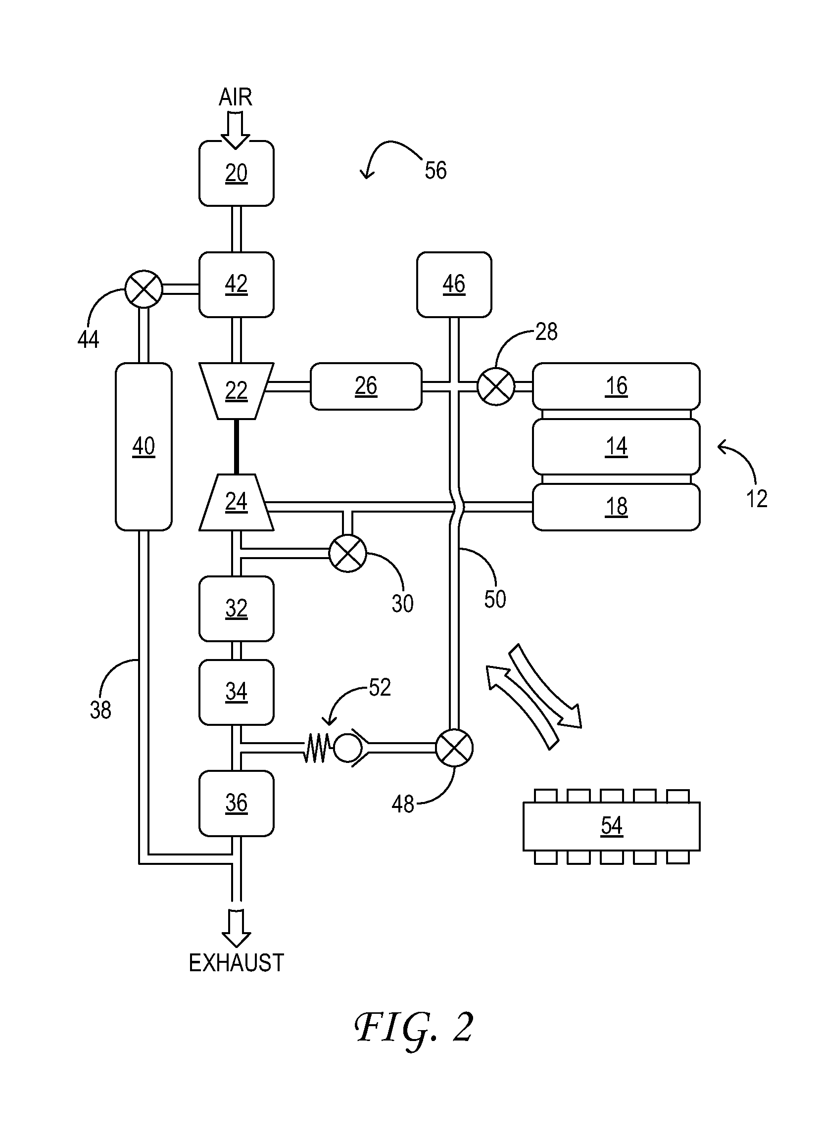
[0004]The inventors herein have recognized that improved transient control in an EGR equipped engine system can be achieved by delivering boosted, EGR-diluted air and fresh air through separate throttle valves. In one embodiment, therefore, a method for providing intake air to an engine in a vehicle comprises forming a mixture of fresh air and treated exhaust, and compressing the mixture upstream of a first throttle valve coupled to an intake manifold of the engine. The method further comprises, during a higher engine-load condition, admitting the mixture to the intake manifold via the first throttle valve, and, during a lower engine-load condition, admitting fresh air to the intake manifold via a second throttle valve. In this manner, pressurized, EGR-diluted air remains trapped behind the first throttle valve, thereby alleviating at least some transient-control difficulties associated with cooled EGR.
[0005]Another method for providing intake air to an engine in a vehicle comprises delivering compressed fresh air and EGR to the engine via first and second throttle valves coupled to an intake manifold of the engine. During a higher engine-load condition, an EGR exhaust flow is cooled in a heat exchanger and the cooled EGR exhaust flow is admitting to the intake manifold. During a lower engine-load condition, fresh air is warmed in the heat exchanger, and the warmed fresh air is admitted to the intake manifold. In this manner, the heat exchanger serves double duty, abating knock at high engine load, and providing other advantages at low engine load. In particular, in the low-load region of the engine map the intake air can be heated to a significant degree without inducing knock; such heating reduces the density of the gas in the intake manifold with little or no reduction in inlet air pressure. Besides reducing pumping losses, increased intake air temperature may improve combustion reliability and increase EGR tolerance.

Problems solved by technology

Such elevated temperatures may contribute to increased nitrogen-oxide (NOX) emissions and may accelerate materials ageing in the engine system, including exhaust-aftertreatment catalyst ageing.
EGR works by delivering exhaust gas having reduced oxygen content to the intake, which results in lower combustion and exhaust temperatures.
However, cooled EGR is liable to cause transient control difficulties in boosted engine systems, particularly in combination with spark-ignition.
Under low-load, closed-throttle conditions, however, the engine may require fresh air to sustain combustion.
Opening a compressor by-pass valve at this time provides a partial, but incomplete remedy for the problem, as the EGR-diluted air remains upstream of the throttle, albeit at a lower absolute pressure.
However, this system is particular to diesel engines, which may be unthrottled, and may tolerate significant amounts of EGR even at idle.

Method used


Image

  • Warming Intake Air Using EGR Cooler in Dual-Throttle Boosted Engine System
  • Warming Intake Air Using EGR Cooler in Dual-Throttle Boosted Engine System
  • Warming Intake Air Using EGR Cooler in Dual-Throttle Boosted Engine System

Examples


Embodiment Construction

[0008]The subject matter of the present disclosure is now described by way of example and with reference to certain illustrated embodiments. Components that may be substantially the same in two or more embodiments are identified coordinately and are described with minimal repetition. It will be noted, however, that components identified coordinately in different embodiments of the present disclosure may be at least partly different. It will be further noted that the drawings included in this disclosure are schematic. Views of the illustrated embodiments are generally not drawn to scale; aspect ratios, feature size, and numbers of features may be purposely distorted to make selected features or relationships easier to see.

[0009]FIG. 1 shows aspects of a first example system 10 configured to provide intake air to an engine 12 in a vehicle. The engine includes a plurality of combustion chambers 14, each coupled to intake manifold 16 and to exhaust manifold 18. In the combustion chamber...


PUM


Abstract

A method for providing intake air to an engine in a vehicle comprises delivering compressed fresh air and EGR to the engine via first and second throttle valves coupled to an intake manifold of the engine. During a higher engine-load condition, an EGR exhaust flow is cooled in a heat exchanger and the cooled EGR exhaust flow is admitting to the intake manifold. During a lower engine-load condition, fresh air is warmed in the heat exchanger, and the warmed fresh air is admitted to the intake manifold.

Description

TECHNICAL FIELD[0001]The present application relates to improving fuel economy and reducing emissions in motor vehicles, and more particularly, to enacting exhaust-gas recirculation in boosted engine systems.BACKGROUND AND SUMMARY[0002]A boosted engine may exhibit higher combustion and exhaust temperatures than a naturally aspirated engine of similar output power. Such elevated temperatures may contribute to increased nitrogen-oxide (NOX) emissions and may accelerate materials ageing in the engine system, including exhaust-aftertreatment catalyst ageing. Exhaust-gas recirculation (EGR) is a popular strategy for combating these effects. EGR works by delivering exhaust gas having reduced oxygen content to the intake, which results in lower combustion and exhaust temperatures. In particular, EGR variants that deliver cooled EGR are desirable because they can supply a relatively large flow of exhaust gas to the intake. However, cooled EGR is liable to cause transient control difficultie...

Claims


Application Information

Patent Timeline
Patent Type & Authority Applications(United States)
IPC IPC(8): F02G5/00F02M25/07F02B23/00F02B33/00
CPCF02B29/0406Y02T10/47F02B47/08F02D21/08F02D41/0002F02D41/0007F02D41/0052F02D41/0077F02D2200/0406F02M25/0707F02M25/0709F02M25/0718F02M25/0722F02M25/073F02M25/0731F02M25/0738F02M25/0742F02M31/07Y02T10/144Y02T10/126Y02T10/42F02B37/18F02M26/05F02M26/06F02M26/15F02M26/19F02M26/27F02M26/28F02M26/33F02M26/36Y02T10/12Y02T10/40
Inventor LIPPA, ALLAN J.PURSIFULL, ROSS DYKSTRAKOTWICKI, ALLAN J.
Owner FORD GLOBAL TECH LLC
Learn More