Specimen retention container

a technology for specimens and containers, applied in the field of specimen storage containers, can solve the problems of inaccurate images, inaccurate margin analysis, and distortion of specimens, and achieve the effects of reducing the likelihood, reducing distortion of tissue specimens, and being convenient to us

Active Publication Date: 2012-04-24
2 VIEW
View PDF36 Cites 24 Cited by
  • Summary
  • Abstract
  • Description
  • Claims
  • Application Information

AI Technical Summary

Benefits of technology

[0006]The present invention is directed to a tissue specimen container for analyzing a tissue specimen, comprising a closeable container including a body and a lid, and further comprising an interior chamber between the lid and the body when the container is in a closed position; wherein the lid comprises a top surface and a first edge; wherein the body comprises a top surface having a second edge and a bottom surface, wherein the bottom surface is defined by a specimen-containing depression; and wherein the interior chamber is adapted to contain the specimen between and in contact with the lid and the body in a known, fixed orientation with minimal compression, minimal movement, and minimal fluid leakage.
[0007]The present invention is further directed to a tissue specimen container for analyzing a tissue specimen, comprising a closeable container including a body and a lid, and further comprising an interior chamber between the lid and the body when the container is in a closed position; wherein the lid comprises a top surface and a first edge; wherein the body comprises a top surface having a second edge and a bottom surface, wherein the bottom surface is defined by a specimen-containing concave depression; wherein the interior chamber is adapted to contain the specimen between and in contact with the lid and the body in a known, fixed orientation with minimal compression, minimal movement, and minimal fluid leakage; wherein the container comprises either a transparent or a translucent material for radiographic imaging; and wherein the first edge of the lid is adapted to be sealingly engaged with the second edge of the body to form a leak-proof seal; and at least one retainer formed of a soft flexible radiographically-transparent material to facilitate the retention of the specimen within the container.
[0008]The present invention is further directed to a method of handling a tissue specimen comprising the following steps: a) placing the specimen inside a tissue specimen container, comprising a closeable container including a body and a lid, and further comprising an interior chamber between the lid and the body when the container is in a closed position; wherein the lid comprises a top surface and a first edge; wherein the body comprises a first radiographically-viewing surface having a second edge, a second radiographically-viewing surface, and a bottom surface, wherein the bottom surface is defined by a specimen-containing depression; and wherein the interior chamber is adapted to contain the specimen between and in contact with the lid and the body in a known, fixed orientation with minimal compression, minimal movement, and minimal fluid leakage; b) closing the lid onto the body such that the specimen is immobilized in the interior of the container; c) placing the container in a first position to produce an x-ray image of the specimen through the first radiographically-viewing surface; and d) placing the container in a second position to produce an x-ray image of the specimen through the second radiographically-viewing surface.

Problems solved by technology

However, this type of device creates distortion of the specimen rendering accurate margin analysis nearly impossible.
It also does not allow for radiologic evaluation in multiple planes unless the specimen is removed and reoriented, which disturbs the specimen enough to render the images inaccurate.
However, this device attempts to reshape the specimen into a rectangular space creating some degree of distortion.
It also fails to prevent the leakage of body fluids thereby exposing the handlers to potential blood borne pathogens.

Method used


Image

  • Specimen retention container
  • Specimen retention container
  • Specimen retention container

Examples


Embodiment Construction

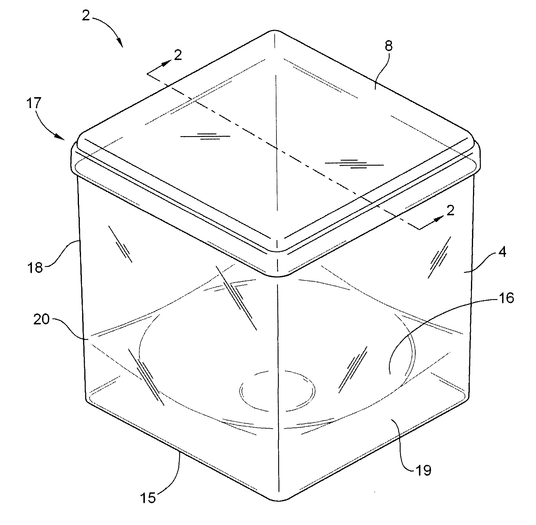
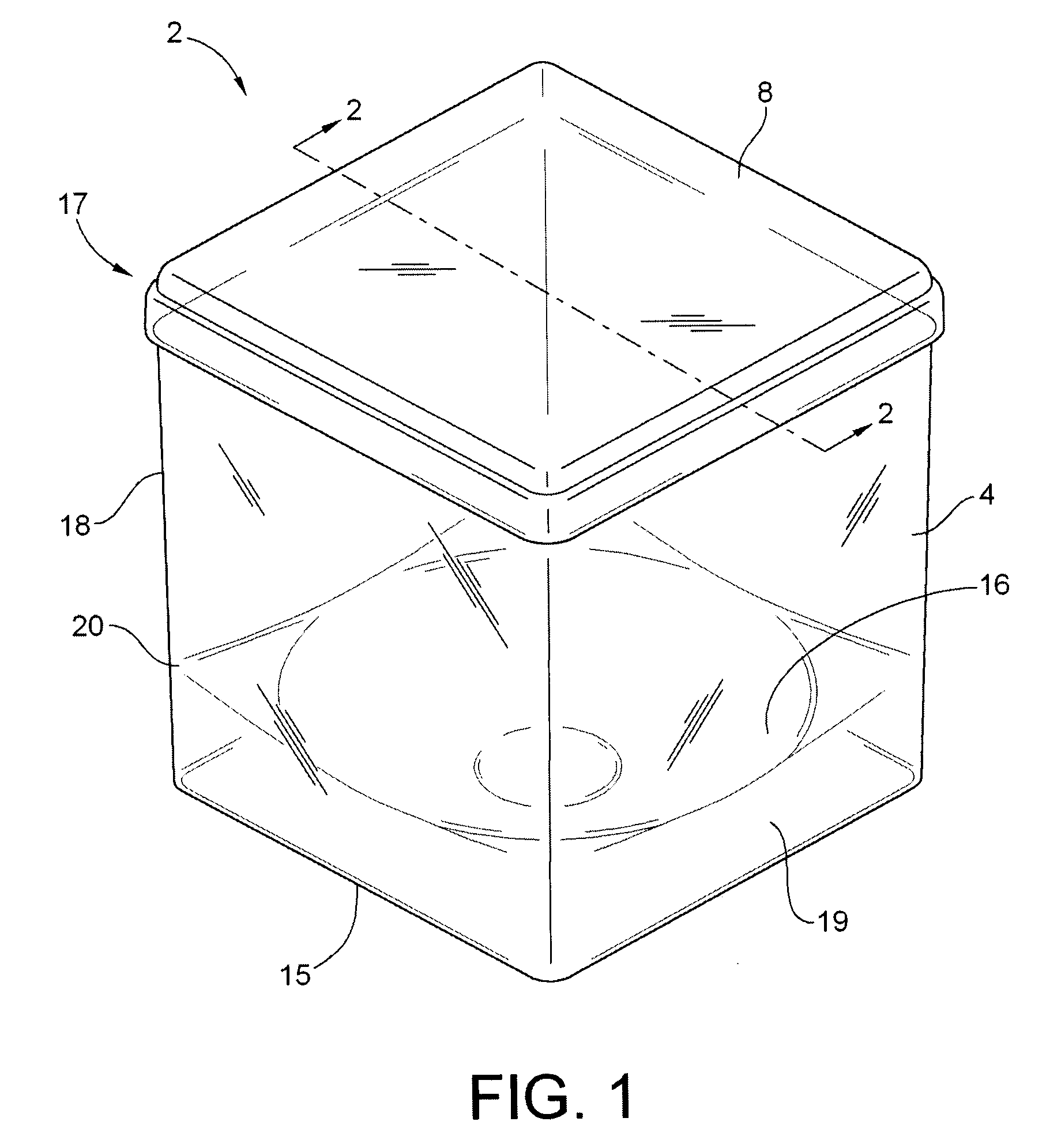
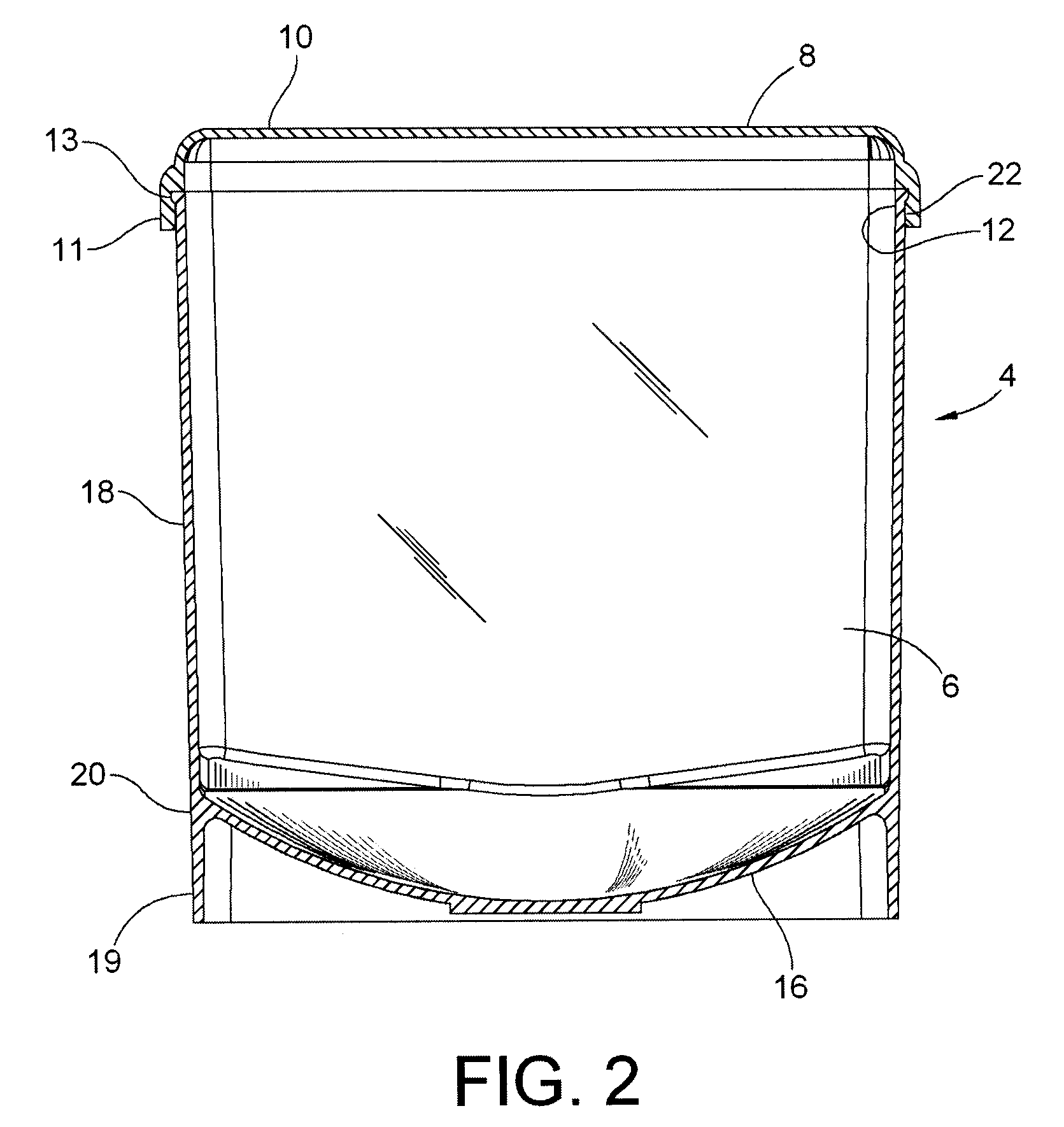
[0022]Referring now to the drawings, FIGS. 1-3 illustrate an assembled view of the components of the specimen retention container 2, which includes a body 4 and a separate lid 8.

[0023]The body 4 is generally boxed-shaped and includes four substantially parallel walls 18 defining an interior 6 of the body 4, a lower end 15 and an open upper end 17. The lower end 15 is defined by a substantially-concave floor 16, which is positioned opposite of the open end 17 and effectively forms an impermeable closed lower end 15. The concave floor 16 is joined to the outer walls 18 at junction 20 at variable positions distant from the open end 17. The upper open end 17 of the container is defined by a lip 2 which extends outwardly from the walls 18 for mating engagement with the lid 8.

[0024]As illustrated in FIG. 1, the junction 20 forms the upper edge of the substantially-concave floor 16. In this configuration, the lower end 15 of the container 2 can sit on a flat surface or plane, parallel and ...


PUM


Abstract

A container and method of using the container to maintain an excised tissue specimen in a fixed orientation during transport and imaging is described. The container includes a body, a flexible, soft retainer capable of holding various sized specimens, an adjustable soft retainer that interacts with the body to retain the specimen against the soft retainer without significant compression or distortion, and a lid that snaps tightly to the body reducing bodily fluid leakage when the container is placed in a horizontal position, and preventing contamination of the specimen.

Description

REFERENCE TO RELATED APPLICATION[0001]The application claims priority to U.S. Provisional Application entitled “Specimen Retention Device,” Ser. No. 60 / 789,668, filed Apr. 6, 2006, which is incorporated herein by reference in its entirety.FIELD OF THE INVENTION[0002]The invention relates to a container to maintain an excised tissue specimen such as an excisional biopsy or partial mastectomy excision in a stable orientation throughout subsequent imaging and transport.DESCRIPTION OF THE PRIOR ART[0003]When a patient is diagnosed with a tissue abnormality and undergoes a surgical procedure for its removal, there are times when it is advisable to take radiographic views of the resected tissue specimen to assess the adequacy of the resection. As used in the present invention, the term “tissue specimen” may refer to a wide variety of animal tissue specimens. Examples include breast tissue and brain or other organ tissue. The term “tissue specimen” can also refer to vegetable tissues. As t...

Claims


Application Information

Patent Timeline
Patent Type & Authority Patents(United States)
IPC IPC(8): A61B17/06
CPCA61B10/0096B01L3/508B01L2300/042B01L2300/0609G01N2001/315
Inventor HANSEN, JOHN G.HENRY, C. ALAN
Owner 2 VIEW
Why Eureka
Try Eureka