Rotary joint assembly and combination clip-hook and jewelry piece employing the same

a technology of rotary joints and clip hooks, which is applied in the direction of snap fasteners, curtain suspension devices, scarves, etc., can solve the problems of soiling and spilled liquid, limited options for doing so, and soiling from spilled liquid

Active Publication Date: 2012-04-24
CLIPSY
View PDF43 Cites 22 Cited by
  • Summary
  • Abstract
  • Description
  • Claims
  • Application Information

AI Technical Summary

Benefits of technology

[0006]This invention overcomes the disadvantages of the prior art by providing a combination clip and hook (clip) or other closable assembly for use generally in suspending articles having shoulder or hand straps, or otherwise carrying accessory items, such as keys, which is rotatably movable about a rotary joint between a first rotational position in which two opposing, rotatably joined portions of the overall clip structure are oriented together to form a continuous, enclosed shape that can be secured around another strap or loop on an item or piece of clothing (e.g. a belt loop), and a second rotational position in which the two portions of the structure are rotated out of the enclosed shape, and into a hook (for example, an S-shaped hook) in which one portion of the structure supports the strap of the item and the other portion can be applied to a clothing hook, chair back, table surface, door top, or other supporting member. In further embodiments, the enclosed structure can define a wearable piece of jewelry that is secured to the wearer's wrist, ankle, neck or other appendage in the enclosed orientation and removable therefrom in the opened orientation. In an illustrative embodiment, the joint between the two portions can define a spring-loaded rotating pivot assembly with at least two indexing positions. The first index position places the portions in the enclosed orientation, with opposing free ends thereof (opposite the joint ends) being in a confronting relationship with a minimal gap therebetween. The second index position orients the two portions approximately 180 degrees opposite the enclosed orientation, thereby allowing the formation of the hook.

Problems solved by technology

This is because such items can contain valuable contents, and may be constructed from expensive materials that are prone to soiling.
Options for doing so are often limited.
The bag or purse can be placed beneath the owners legs, rendering it subject to soiling and spilled liquid.
Alternatively, it can be placed on the table or countertop, where it becomes intrusive and may also be subject to soiling from spilled liquid and food.
Typically, this entails delicate hinges and cumbersome clasps, many of which are prone to breakage and otherwise difficult to manipulate.

Method used


Image

  • Rotary joint assembly and combination clip-hook and jewelry piece employing the same
  • Rotary joint assembly and combination clip-hook and jewelry piece employing the same
  • Rotary joint assembly and combination clip-hook and jewelry piece employing the same

Examples


Embodiment Construction

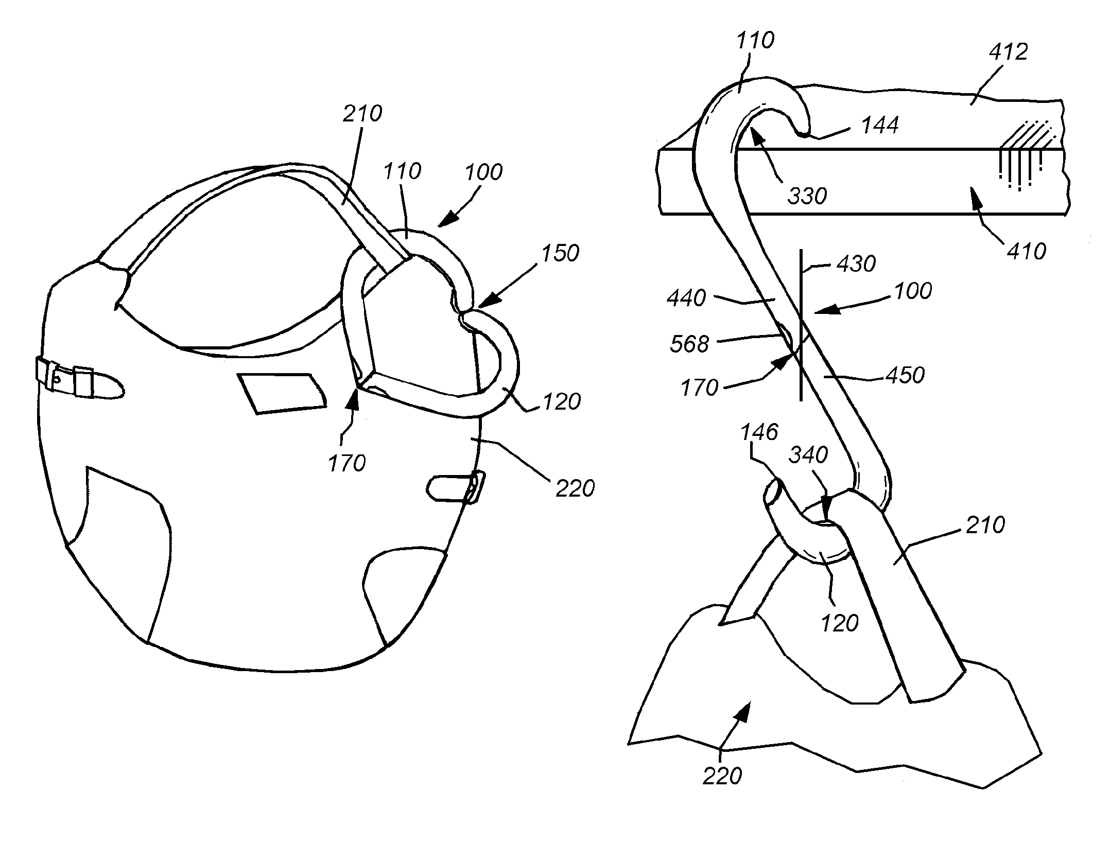
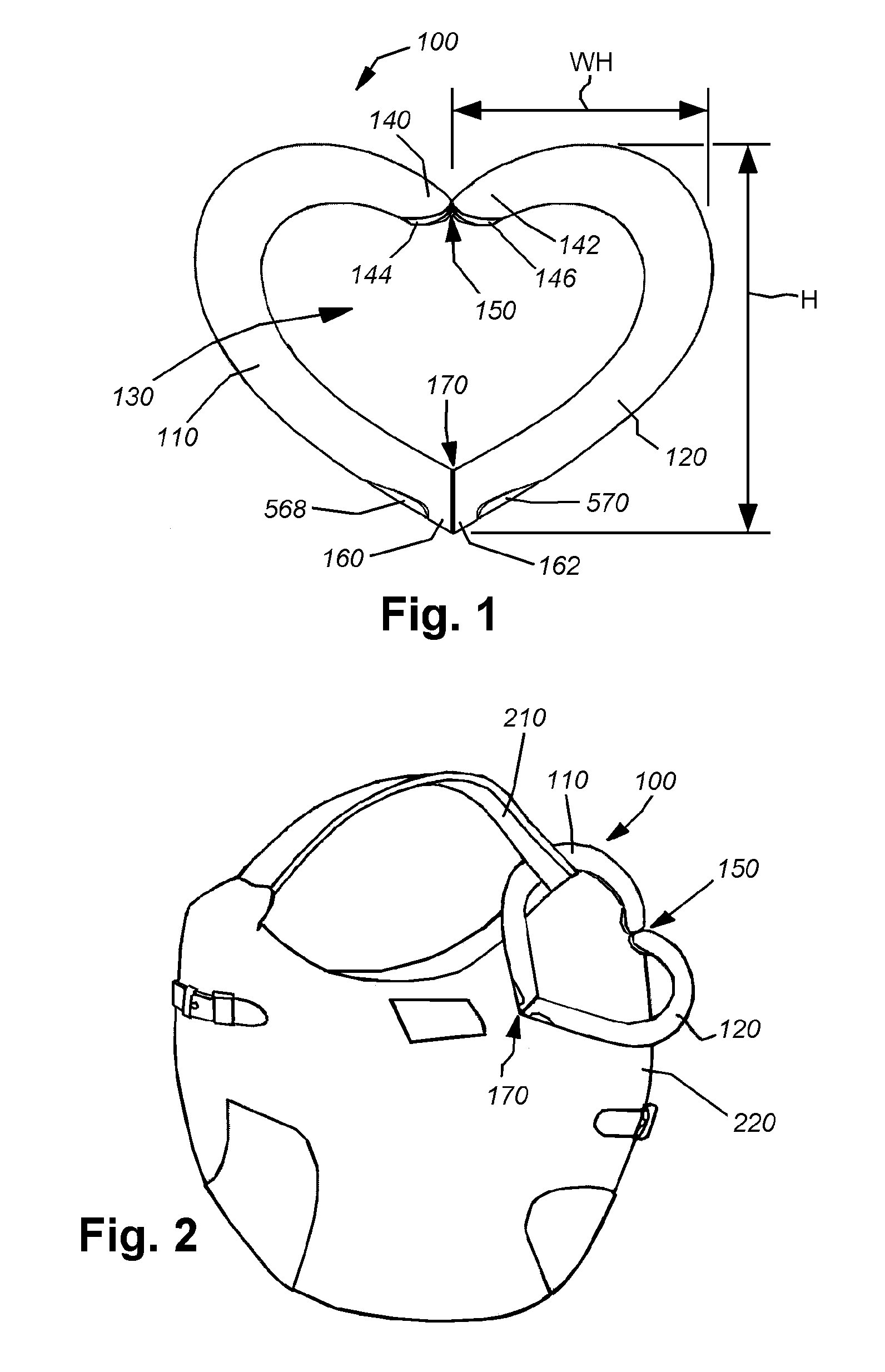
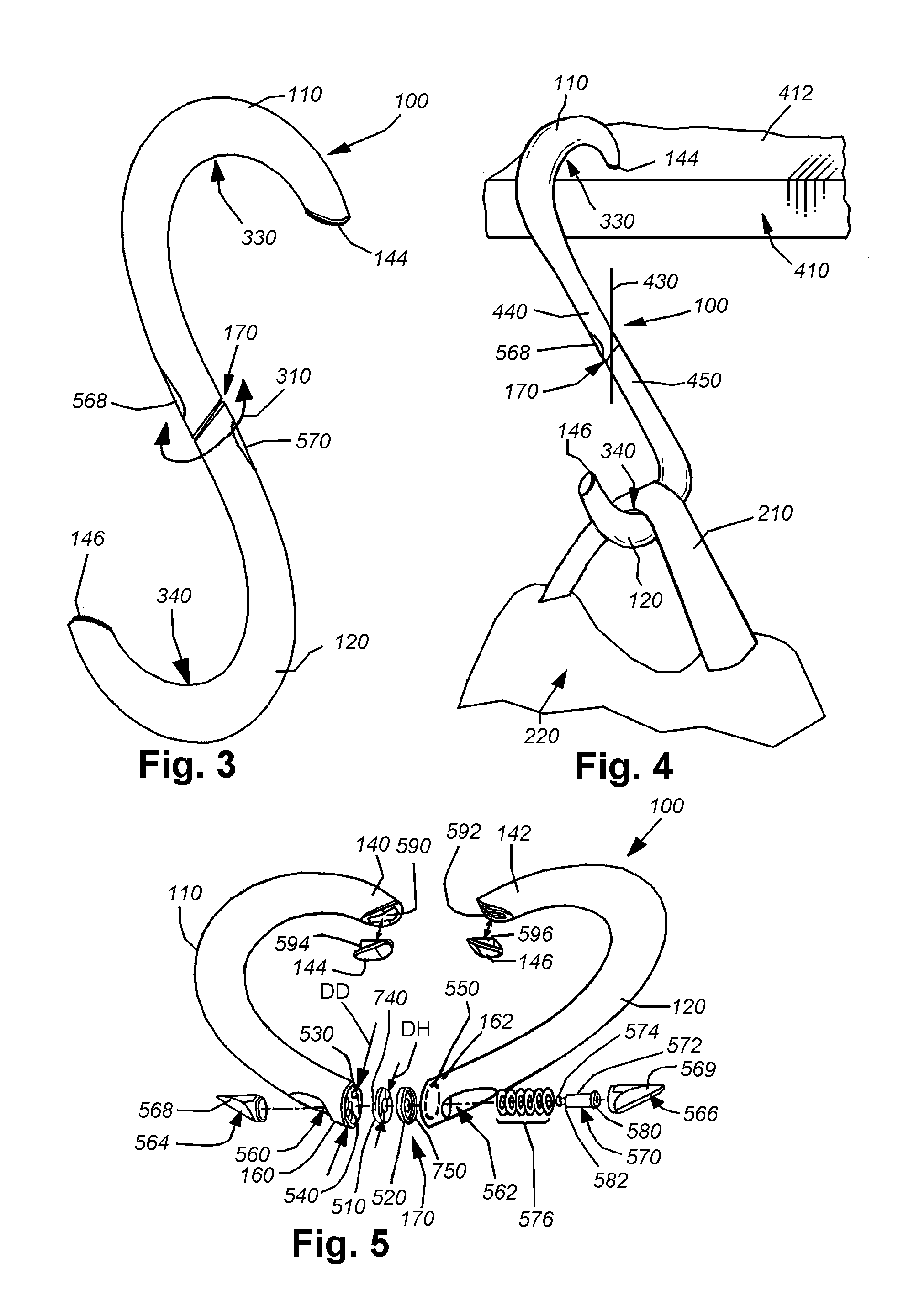
[0034]FIG. 1 shows a clip and hook structure 100 in side view according to an illustrative embodiment of this invention. Notably, the clip and hook structure 100 (also termed herein the “clip”) consists of a pair of portions 110 and 120—each defining a substantial mirror image of the other's outline perimeter shape. Each portion 110, 120 in this embodiment forms one half of an overall heart-shaped outline in this embodiment. Each clip portion 110, 120 defines a maximum width WH of approximately 50-60 mm in this embodiment and a height H of approximately 70-90 mm in this embodiment. Of course, the actual width and height are highly variable in alternate embodiments. In general, the chosen width and height provides an interior region 130 when enclosed as shown that is sufficient to clear a handle, shoulder strap, or other carrying member of a bag, luggage piece or other hand / shoulder-carried item. The width WH also allows for a hook shape (as described below) that is sufficiently larg...


PUM


Abstract

A combination clip and hook (clip) for use generally in suspending articles, which is rotatably movable about a rotary joint between a first position in which two opposing, rotatably joined portions of the overall clip structure are oriented together to form a continuous, enclosed shape that can be secured around another, and a second position in which the two portions of the structure are rotated out of the enclosed shape, and into, for example, a S shaped hook where one portion of the structure supports the item and the other portion can be applied to another supporting member. The joint between the two portions can define a spring-loaded rotating pivot assembly with at least two indexing positions opposed by 180 degrees. The rotary joint can be constructed with a pair of confronting male and female wedge and detent inserts that are biased toward each other by an embedded spring assembly.

Description

RELATED APPLICATION[0001]This application claims the benefit of U.S. Provisional Application Ser. No. 61 / 101,104, entitled COMBINATION CLIP AND HOOK FOR PURSES, BAGS AND ACCESSORIES, by Farvardin Fahti Kamangar, et al., filed Sep. 29, 2008, the teachings of which are expressly incorporated herein by reference.FIELD OF THE INVENTION[0002]This invention relates to detachable accessories for use with purses, bags and other items having a carrying handle or strap, and more particularly to hanging hooks for bags, and the like as well as other accessories that employ a movable joint to change orientations of components thereof.BACKGROUND OF THE INVENTION[0003]Hooks and clips are commonly used items in daily life. They allow items to be secured together when desired. They also allow items to be hung from a suspended surface to as to avoid placing the item on a dirty floor or other surface. It is particularly desired to elevate purses, bags, and other hand-and-shoulder-carried effects above...

Claims


Application Information

Patent Timeline
Patent Type & Authority Patents(United States)
IPC IPC(8): F16B45/00
CPCA44B15/005A47G29/083B67B7/16Y10T24/3487Y10T24/3488Y10T24/13Y10T403/32827Y10T24/3485Y10T403/32541Y10T403/32852
Inventor FATHI, FARVARDINAZIZ, IMRAANSTRASSER, MICHAEL J.KING, THOMAS E.
Owner CLIPSY
Why Eureka
Try Eureka