Orthopedic rod system

a technology of rods and pedicle screws, which is applied in the field of orthopedic implantable devices, can solve the problems of difficult task, difficult installation and cross-threading, and require costly and precise tolerances, and achieve the effect of minimal sizing of the screw head and maximum alignment of the locking for

Active Publication Date: 2012-04-24
ALTUS PARTNERS
View PDF33 Cites 87 Cited by
  • Summary
  • Abstract
  • Description
  • Claims
  • Application Information

AI Technical Summary

Benefits of technology

[0009]Another aspect of the present invention, specifically directed to the embodiments described below relating to multi-axis systems, provides that due to the novel design of a seated bone screw, maximum alignment of locking forces can be achieved with minimal sizing of a screw head.

Problems solved by technology

This task is difficult since the surgeon must manipulate and tighten the cap while holding the pedicle screw and rod at a particular desired angle.
Associated problems are difficulty of installation and cross-threading.
Such designs require costly and precise tolerances and are difficult to use during surgery.

Method used


Image

  • Orthopedic rod system
  • Orthopedic rod system
  • Orthopedic rod system

Examples


Embodiment Construction

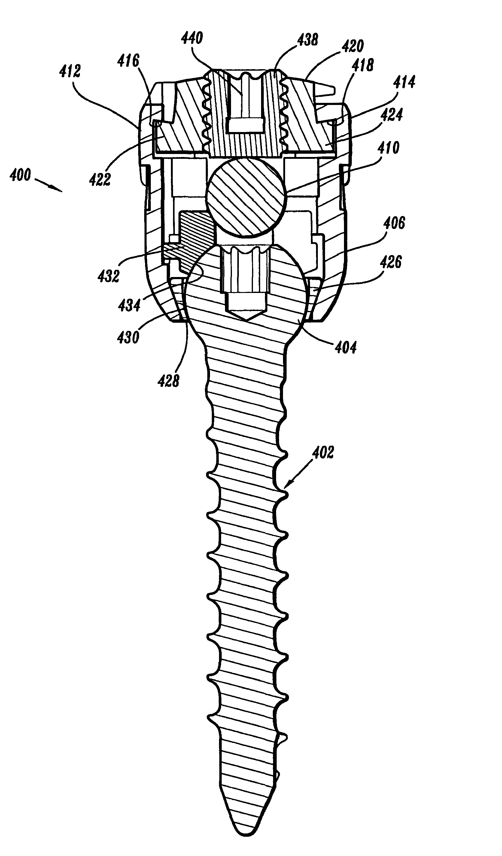
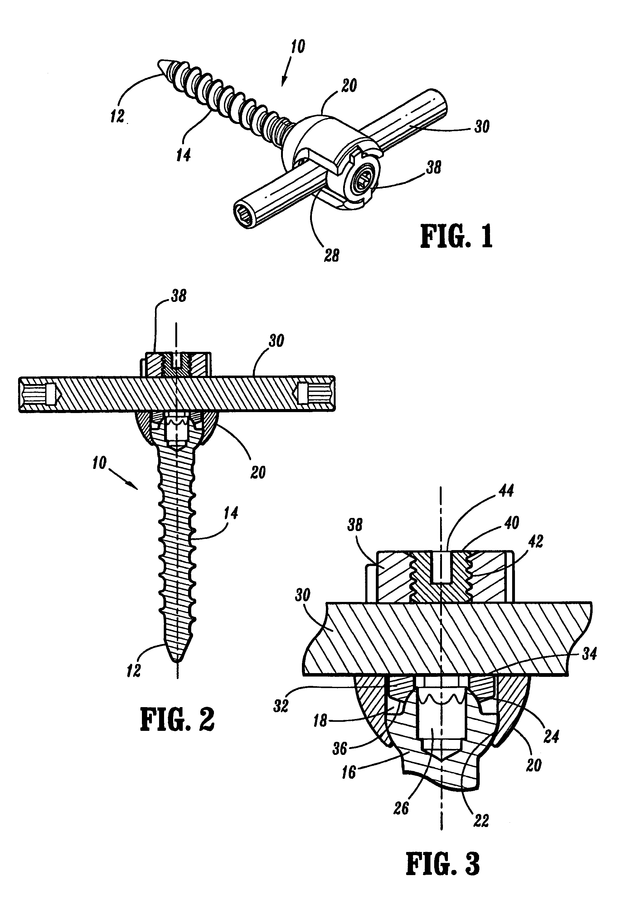
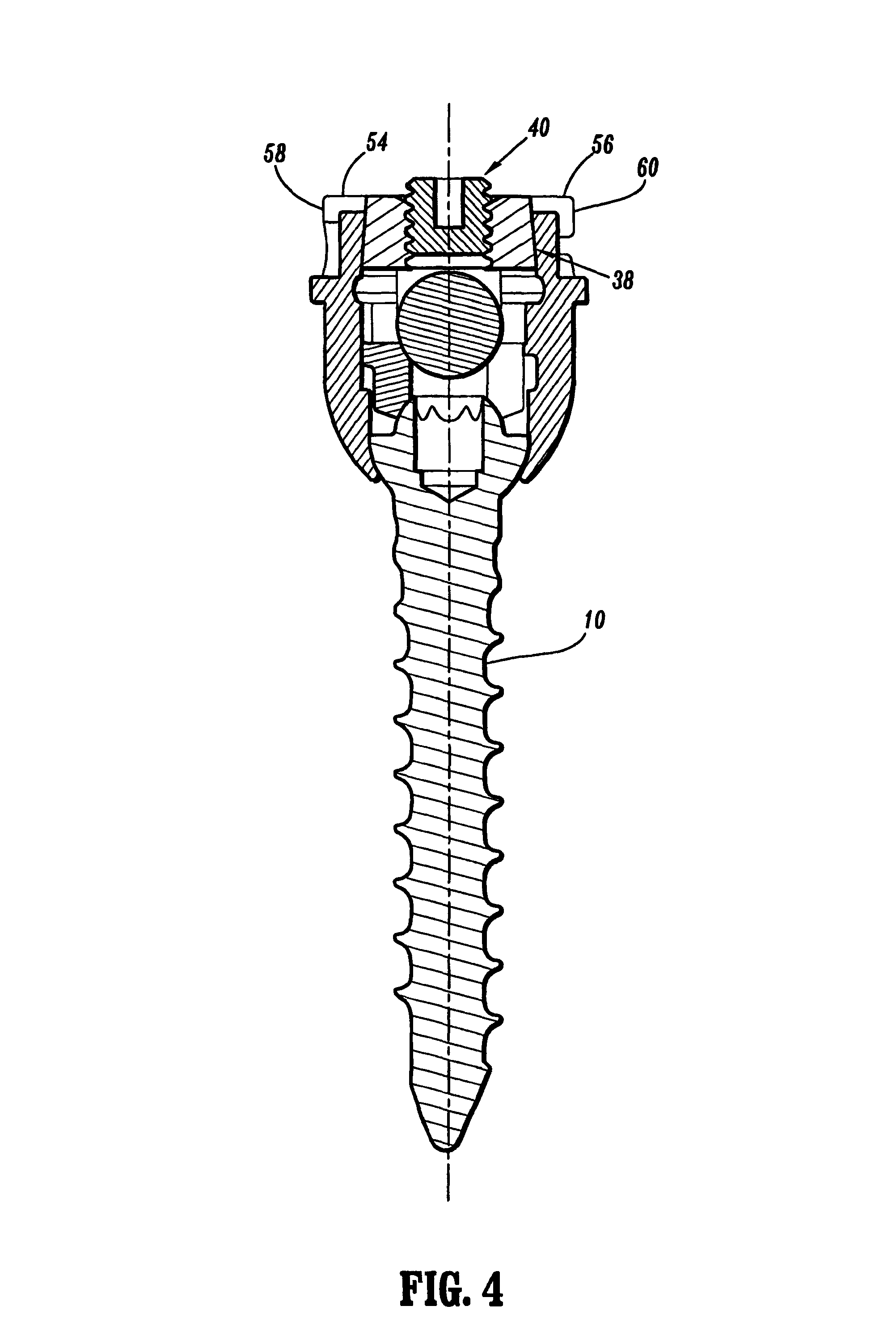
[0023]Referring to FIGS. 1-3, a pedicle screw (10) according to the present invention includes a first end (12) adapted to be driven into bone, a threaded intermediate portion (14), and a head (16) having a semicircular profile. The screw (10) is positioned through a central opening (18) in a rod-receiving cup (20). The cup (20) has a lower, conical interior surface (22) that the head (16) pivotally rests in. The head (16) also includes a dome top (24) and a driver-engaging socket (26).

[0024]The cup (20) has two opposed slots (28) forming a yoke through which a rod (30) is received. A lower surface (36) of a seat element (32) rests in slideable contact with the dome top (24) of the screw head (16). The upper surface (34) of the seat element (32) contacts the rod (30). An upper cap (38) is received in the upper end of the cup (20) above the rod (30). A locking threaded screw (40) having a tool engaging socket (44) is tightened through a central, threaded opening (42) in the cap (38) ...


PUM


Abstract

A tulip-shaped rod-receiving member in a spinal rod system is provided with a transverse slot accessible from the top of the tulip member for placing the rod therein until the rod seats. A locking assembly includes a cap having inclined surfaces that cooperate with inclined surfaces on the rod-receiving member to lock and bias inwardly the rod-receiving member relative to the cap. A novel seating ring is provided for the bone screw to be supported in the tulip in a manner that maximizes support and optimizes axial alignment of forces.

Description

RELATED APPLICATIONS[0001]This application is related to, and claims priority from, the following earlier-filed U.S. Provisional Patent Applications: (Ser. Nos.) 60 / 423,168 (filed 4 Nov. 2002); 60 / 479,822 (filed 20 Jun. 2003). Each is incorporated herein by reference.TECHNICAL FIELD[0002]The present invention relates to orthopedic implantable devices, related systems, and associated methods of use and, more particularly, to a pedicle screw and rod system and associated method for joining two or more bone segments, such as vertebrae.BACKGROUND OF THE INVENTION[0003]Pedicle screw systems used for fastening spinal rod systems to the pedicle region of two or more vertebral bodies exist in a variety of forms. Successive designs have strived to attain optimal levels of performance, costs, and ease of use. Some known pedicle screw systems provide a locking cap that is threadingly received into a holding sleeve. To lock the pedicle screw relative to the rod the cap is placed into the sleeve...

Claims


Application Information

Patent Timeline
Patent Type & Authority Patents(United States)
IPC IPC(8): A61B17/70
CPCA61B17/7032A61B17/7037A61B17/7002
Inventor KHALILI, FARID BRUCE
Owner ALTUS PARTNERS
Why Eureka
Try Eureka