Orbital track wind turbine

a wind turbine and orbital track technology, applied in the direction of renewable energy generation, electric generator control, greenhouse gas reduction, etc., can solve the problems of low efficiency, low efficiency, and no amount of political action can achieve long-term success of wind power generation in the long term

Inactive Publication Date: 2012-04-24
EXQUADRUM
View PDF49 Cites 26 Cited by
  • Summary
  • Abstract
  • Description
  • Claims
  • Application Information

AI Technical Summary

Benefits of technology

[0033]In a sixth preferred embodiment, there is provided in connection with the fifth preferred embodiment, an improvement wherein said pair of vertical airfoils are pivotal along their vertical axis, whereby adjustment of the pitch of the airfoils can be made to facilitate the most efficient capture of wind power by the airfoils.
[0034]In a seventh preferred embodiment, there is provided in connection with the sixth preferred embodiment, an improvement wherein each pair of vertical airfoils are pivotal along their vertical axis until the leading edges thereof approach one another, and the cross-section of these airfoils form a V-shape to facilitate initiation of rotation.
[0042]In a fifteenth preferred embodiment, there is provided in connection with the fourth preferred embodiment, an improvement wherein the grooved rollers on the trucks are formed of 4130 chrome alloy steel, whereby to minimize rotational friction with the truck while matching material hardness to its mating surface to decrease cyclical wear and tear.
[0044]In a seventeenth preferred embodiment, there is provided in connection with the sixteenth preferred embodiment, an improvement wherein the vertical airfoils have profile cut foam core which are first covered with carbon fiber unidirectional doublers to combat bending stresses followed by an outer layer of woven fabric to resist tortional loading, followed by a layer of mylar to provide a smooth finish.
[0045]In an eighteenth preferred embodiment, there is provided in connection with the seventeenth preferred embodiment, an improvement wherein the vertical airfoil is vacuum bagged to evenly squeeze excess epoxy resin from the impregnated fabric.
[0048]In the orbital track turbine of the present invention operating in the Savonius mode, the double airfoils are in a “V” shape but there is a gap left at the vertex of the “V”. This gap allows air to trickle in and relieve the vacuum, but does not substantially reduce performance. Large amounts of air (which would rob performance) cannot move through this gap rapidly because of viscous effects. However, the small amounts of air needed to negate a partial vacuum can get through, which results in a substantial improvement in efficiency. In the orbital track turbine of the present invention, it is possible to transition from the “V” / Savonius configuration to the parallel / biplane configuration once the wind conditions are high enough and the turbine has achieved a sufficiently high Tip Speed Ratio (TSR).

Problems solved by technology

Unless wind power is cost competitive, no amount of political action can make it successful in the long term.
The primary and overriding issue in transition to wind power is the cost per kilowatt-hour of electrical power produced by wind in comparison to more conventional electric power generation systems.
However, it has been demonstrated that in the turbines of Savonius the tip speed of the turbines is never faster than the wind, resulting in lower efficiencies.
However, there may be limits to this approach.
One of the problems with the H-rotor is the long radial supports, which create drag and interfere with the turbine's efficiency.
Therefore, engineers have realized that there is a major issue of wind interference in H-rotor designs involving the use of long radial arms to connect the blades to a central axis.
As a result, it has been found that the H-rotor wind turbines are typically about one-third less efficient than wind turbines employing a horizontal rotor.

Method used


Image

  • Orbital track wind turbine
  • Orbital track wind turbine
  • Orbital track wind turbine

Examples


Embodiment Construction

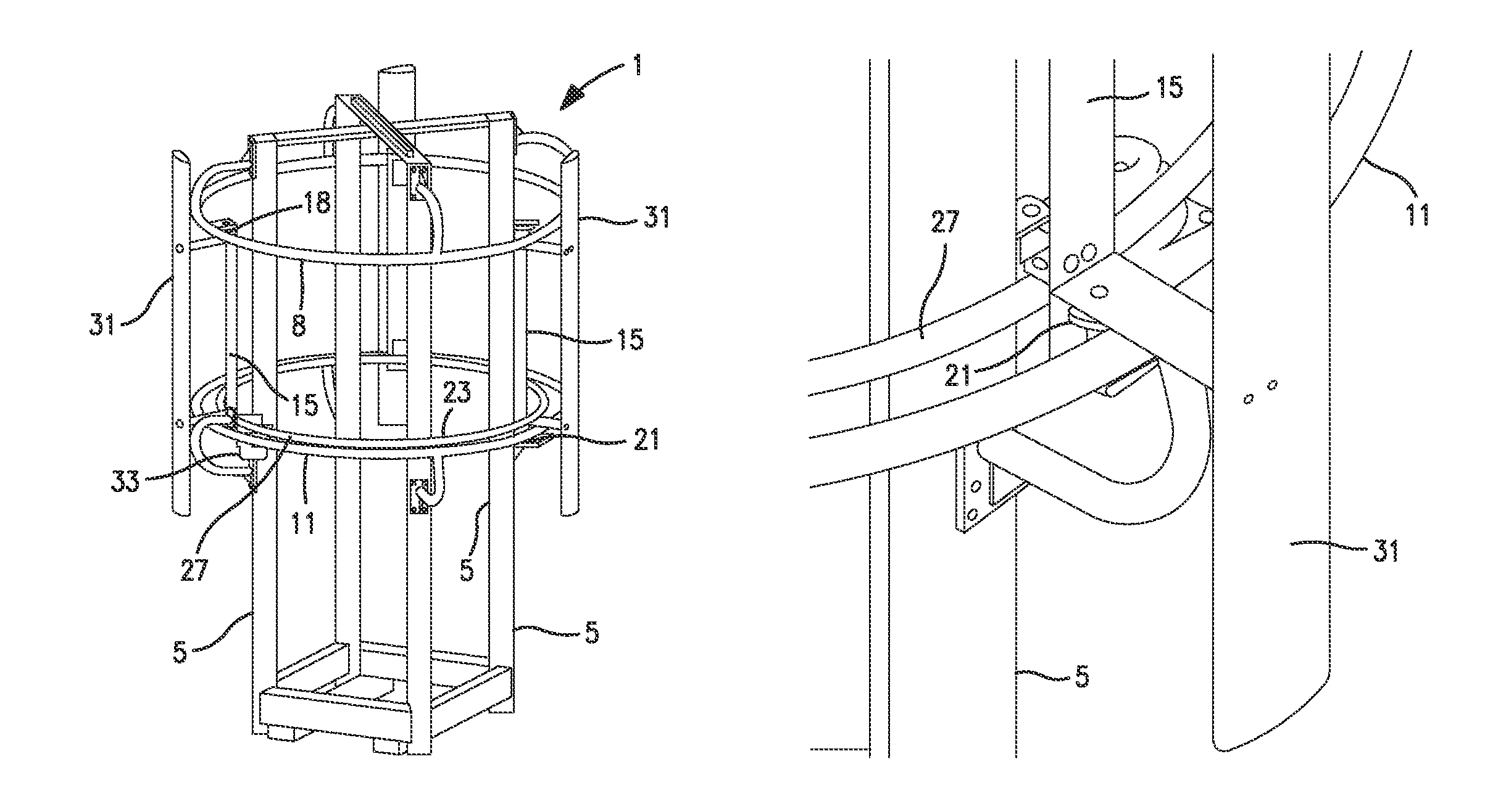
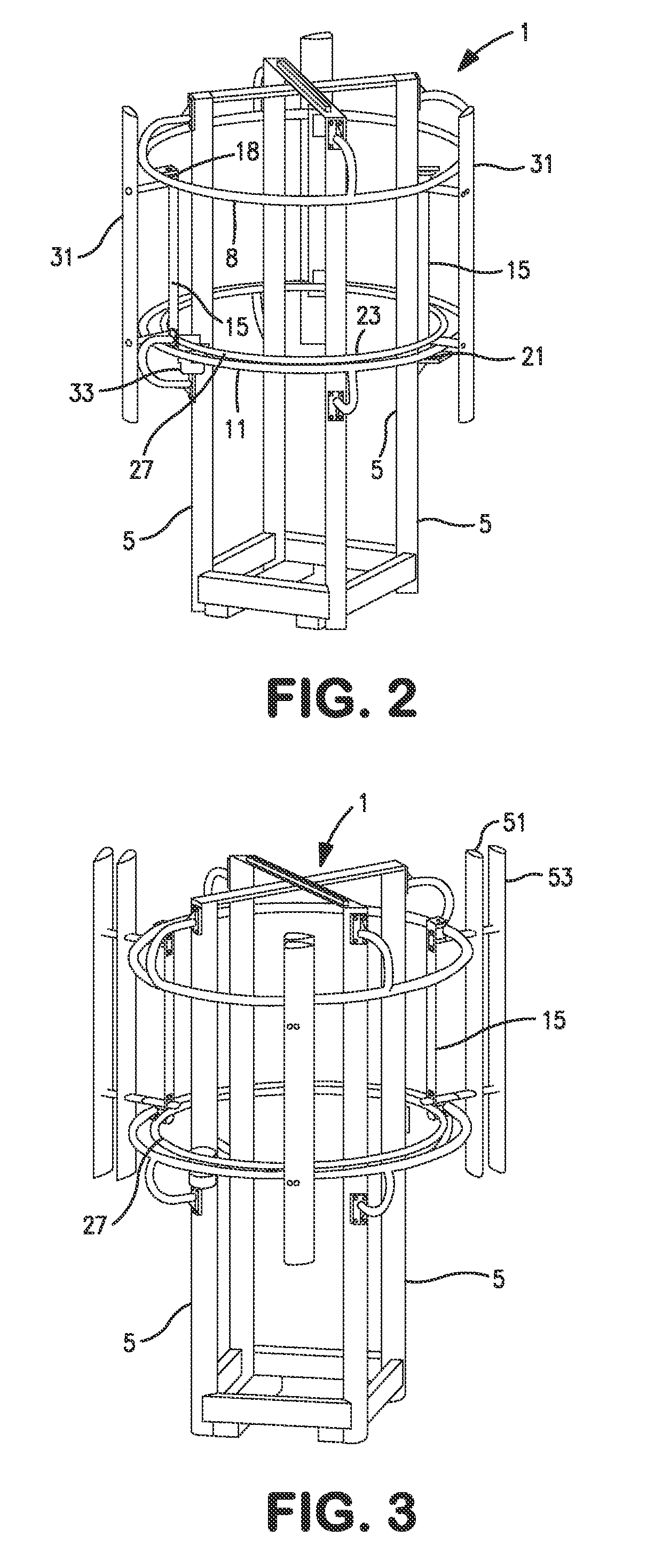
[0078]An orbital track wind turbine according to the present invention is shown generally at 1 in perspective view FIG. 2. The entire wind turbine is supported by a plurality of vertical supports 5 which are normally anchored to the ground by a solid foundation (not shown). The number and spacing of vertical supports varies depending upon the diameter and height of the wind turbine 1, the only limitation being that a sufficient number of vertical supports be used to hold the orbital track turbine solidly in place.

[0079]Fixedly mounted on vertical supports 5 are at least two parallel spaced circular tracks, an upper circular track 8 and a lower circular track 11. Circular tracks 8 and 11 are coaxial with one another and are positioned on the vertical supports 5 in parallel horizontal planes (not shown). Although the circular tracks 8 and 11 can be of any suitable material and have any suitable cross-sectional shape, it is preferred that the tracks be formed from round steel pipe.

[008...


PUM


Abstract

An orbital track wind turbine for generation of electrical energy from wind power is provided. The wind turbine includes a plurality of spaced vertical supports to which at least two parallel spaced circular tracks are fixedly secured. These circular tracks are coaxial with one another and are positioned in parallel horizontal planes. A plurality of trucks extend between the circular tracks, the trucks having at least two grooved rollers which partially surround the circular tracks and operate in rolling engagement therewith. A circular power takeoff ring is coaxial with said circular tracks, and the power takeoff ring is attached to the truck which is rotatable in a horizontal plane about its central axis. A plurality of vertical airfoils extends around the circular power takeoff ring, with each of the airfoils being attached to a truck and the power takeoff ring. One or more generators are connected to the power takeoff ring, thereby converting wind generated rotation of the power takeoff ring to electrical energy.

Description

STATEMENT OF GOVERNMENT INTEREST[0001]This invention was in part made with government support under contract No. 2008-33610-18889 awarded by the United States Department of Agriculture. The government has certain rights in the invention.BACKGROUND OF THE INVENTION[0002]1. Field of the Invention[0003]The present invention relates in general to the conversion of wind energy to electrical energy and, more particularly, to an orbital track wind turbine which provides a highly efficient method and apparatus for the conversion of wind energy to electrical energy.[0004]2. Description of Related Art[0005]It has become increasingly important due to environmental and economic considerations for the United States to transition from fossil fuels to renewable energy. Unless wind power is cost competitive, no amount of political action can make it successful in the long term. The primary and overriding issue in transition to wind power is the cost per kilowatt-hour of electrical power produced by...

Claims


Application Information

Patent Timeline
Patent Type & Authority Patents(United States)
IPC IPC(8): F03D9/00H02P9/04F03B9/00
CPCF03D3/005F03D5/04F03D7/06F03D9/25Y02E10/70Y02E10/74F05B2240/214F03D15/00
Inventor MAHAFFY, KEVIN E.SCHMIDT, ERIC E.HOWARD, RICKYHENNING, BYRON
Owner EXQUADRUM
Why Eureka
Try Eureka