
Apparatus, method for detecting critical areas and pedestrian detection apparatus using the same

a technology of critical areas and apparatus, applied in the direction of pedestrian/occupant safety arrangement, instruments, scene recognition, etc., can solve the problems of the failure of the conventional pedestrian detection system to produce optimal approaches, and achieve the effect of improving timing performan

Active Publication Date: 2012-04-24
HL KLEMOVE CORP
View PDF5 Cites 152 Cited by
  • Summary
  • Abstract
  • Description
  • Claims
  • Application Information

AI Technical Summary

Benefits of technology

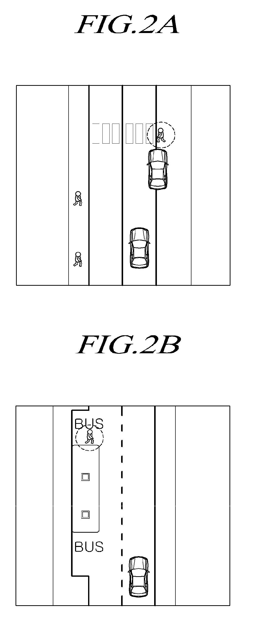
The present patent is about a new technology for detecting pedestrians around vehicles in urban scenarios. The technology uses a critical area detector to identify specific environments and areas around moving obstacles. This allows for the prioritization of searches for pedestrians in close proximity to vehicles or in invisible areas behind the vehicles. The technology also includes an image generator for capturing images of the vehicle's environment and a sensor for sensing obstacles about the vehicle. The critical area detector uses the distance data from the sensor to identify the vehicle's environment and the areas surrounding the moving obstacles. The technology also includes a method for detecting multiple categories of obstacles and identifying critical areas through the classification of the obstacles. Overall, the technology improves traffic safety and prevents collisions with vulnerable road users.

Problems solved by technology

These approaches of the conventional pedestrian detection systems fail to produce an optimal result because they are adapted to recognize certain generic urban environments and detect pedestrians in a large area ahead of the vehicle.

Method used


Image

  • Apparatus, method for detecting critical areas and pedestrian detection apparatus using the same
  • Apparatus, method for detecting critical areas and pedestrian detection apparatus using the same
  • Apparatus, method for detecting critical areas and pedestrian detection apparatus using the same

Examples


Embodiment Construction

I. Introduction

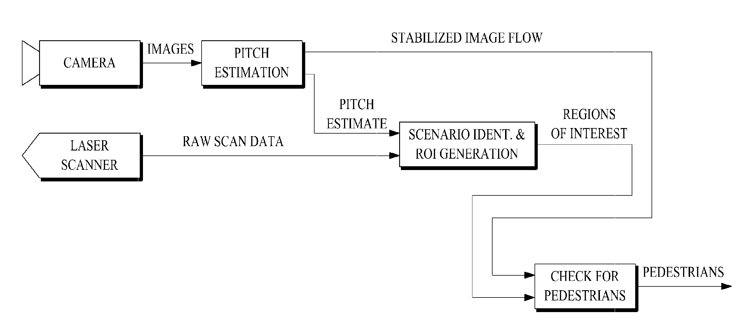
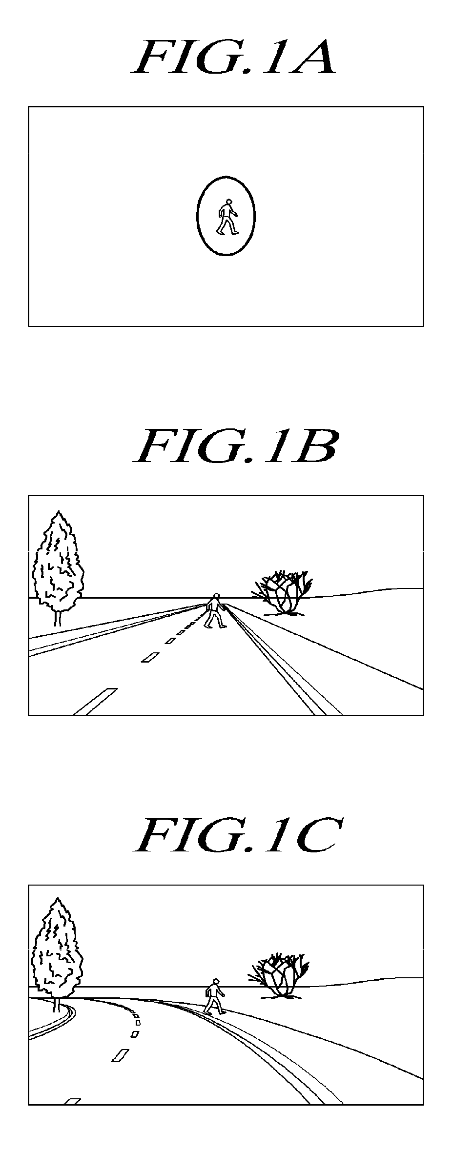
[0026]The present disclosure suggests a pedestrian detection system based on a new approach. In particular, the present disclosure is devised to work in a particularly challenging urban scenario, in which traditional pedestrian detection approaches could not yield optimal results. Moreover, instead of searching for pedestrians in a large area ahead of the vehicle with the system and in a generic urban situation, the system of the present disclosure focuses on a specific scenario in which not only the detection of a pedestrian is of basic importance, but the danger of the situation can be clearly assessed as well.

[0027]In fact, in an automotive system, a correct detection is just the first phase of a successful product: the localization of a traffic sign / traffic light / obstacle or pedestrian with no corresponding indication on its position with respect to the vehicle and the environment provides very little information, which makes the detection system incomplete. As an...


PUM


Abstract

An apparatus, method for detecting critical areas and a pedestrian detection apparatus using the same are provided. An application of the pedestrian detection system is provided to help limit critical urban environment to particular areas. Contrary to traditional pedestrian detection systems that localize every pedestrians appearing in front of the subject vehicle, the apparatus first finds critical areas from urban environment and performs a focused search of pedestrians. The environment is reconstructed using a standard laser scanner but the subsequent checking for the presence of pedestrians is performed by incorporating a vision system. The apparatus identifies pedestrians within substantially limited image areas and results in boosts of timing performance, since no evaluation of critical degrees is necessary until an actual pedestrian is informed to the driver or onboard computer.

Description

TECHNICAL FIELD[0001]The present invention relates to an apparatus, method for detecting critical areas and a pedestrian detection apparatus using the same. More particularly, the present invention relates to an apparatus for protecting pedestrians by first locating environmental barriers of a subject vehicle and then searching for pedestrians among the barriers and a method therefor.BACKGROUND OF THE DISCLOSURE[0002]Traditional pedestrian detection systems are based on searches for all of the pedestrians appearing in front of the vehicle. In such pedestrian detection systems, candidate pedestrians are located using human characteristics such as legs' motion pattern, symmetry, shape, motion and periodicity. When fusion between different sensing technologies was used, the respective sensors search out pedestrian-specific features while becoming a high or a low level.[0003]These approaches of the conventional pedestrian detection systems fail to produce an optimal result because they ...

Claims


Application Information

Patent Timeline
Patent Type & Authority Patents(United States)
IPC IPC(8): B60Q1/00
CPCG01S17/023G01S17/936G06K9/00201G06K9/00369G06K9/00805G08G1/165G08G1/166G08G1/167G01S17/86G01S17/931G06V20/64G06V40/103G06V20/58B60R21/34B60R21/01B60R21/0134
Inventor BROGGI, ALBERTOCERRI, PIETROJUNG, HO-GI
Owner HL KLEMOVE CORP
Learn More