
Method for controlling the movement of a mobile part of an x-ray recording system, and an x-ray recording system coupled to video cameras

a technology of x-ray recording system and x-ray imaging system, which is applied in the field of controlling the movement of the moveable part of the x-ray imaging system as well as the x-ray imaging system, can solve the problems of time-consuming test run, delay in the performance of the test, and difficulty for operators to predict, so as to prevent the movement of the targ

Active Publication Date: 2012-04-24
SIEMENS HEALTHCARE GMBH
View PDF12 Cites 2 Cited by
  • Summary
  • Abstract
  • Description
  • Claims
  • Application Information

AI Technical Summary

Benefits of technology

The invention provides a method for controlling the movement of a moveable part of an x-ray imaging system that does not show the disadvantages of previous methods. The method involves using multiple video cameras to capture the space around the moveable part and determine which parts of the space will be occupied by objects. The system can then decide to allow or prevent the movement of the moveable part based on this information. The method allows for faster and more efficient movement of the moveable part and reduces the risk of collisions with obstacles. It also allows for quicker and more frequent position changes, which is important in a medical setting. The system includes a control facility that analyzes the images from the video cameras and determines which parts of the space will be occupied during the movement of the moveable part. This information is used to enable or disable the movement of the moveable part. Overall, the invention provides a reliable and efficient method for controlling the movement of a moveable part in an x-ray imaging system.

Problems solved by technology

It is not easy for an operator to predict whether or not the moveable part meets with an obstacle during its movement.
The test run is time-consuming which is then particularly troublesome if the x-ray imaging system conducts an interventional operation on the patient, which is then namely delayed in its performance.
In the event of a slow test run, this also does not guarantee that an accident of whatever nature does not take place despite the slow rate.

Method used


Image

  • Method for controlling the movement of a mobile part of an x-ray recording system, and an x-ray recording system coupled to video cameras
  • Method for controlling the movement of a mobile part of an x-ray recording system, and an x-ray recording system coupled to video cameras

Examples


Embodiment Construction

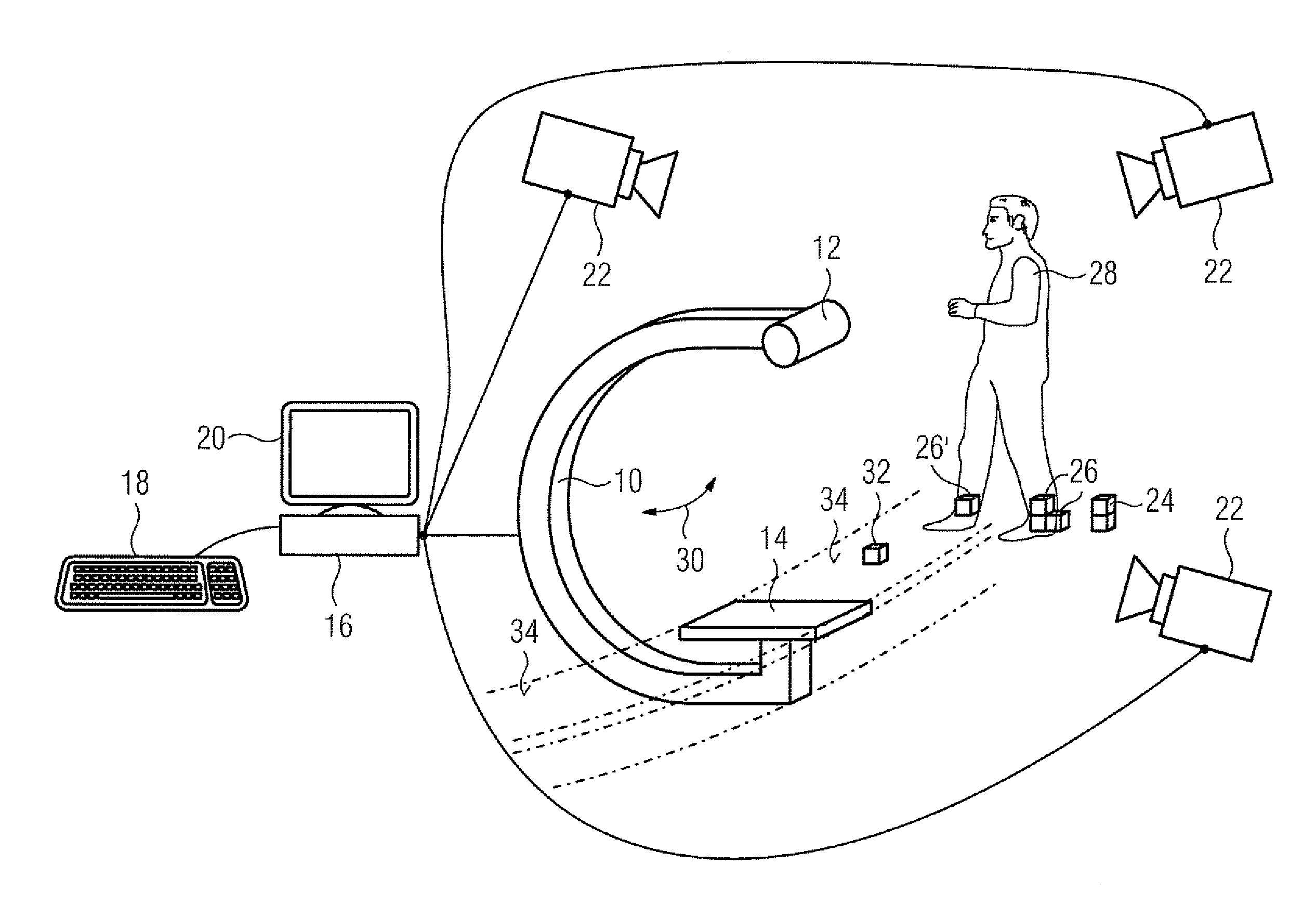
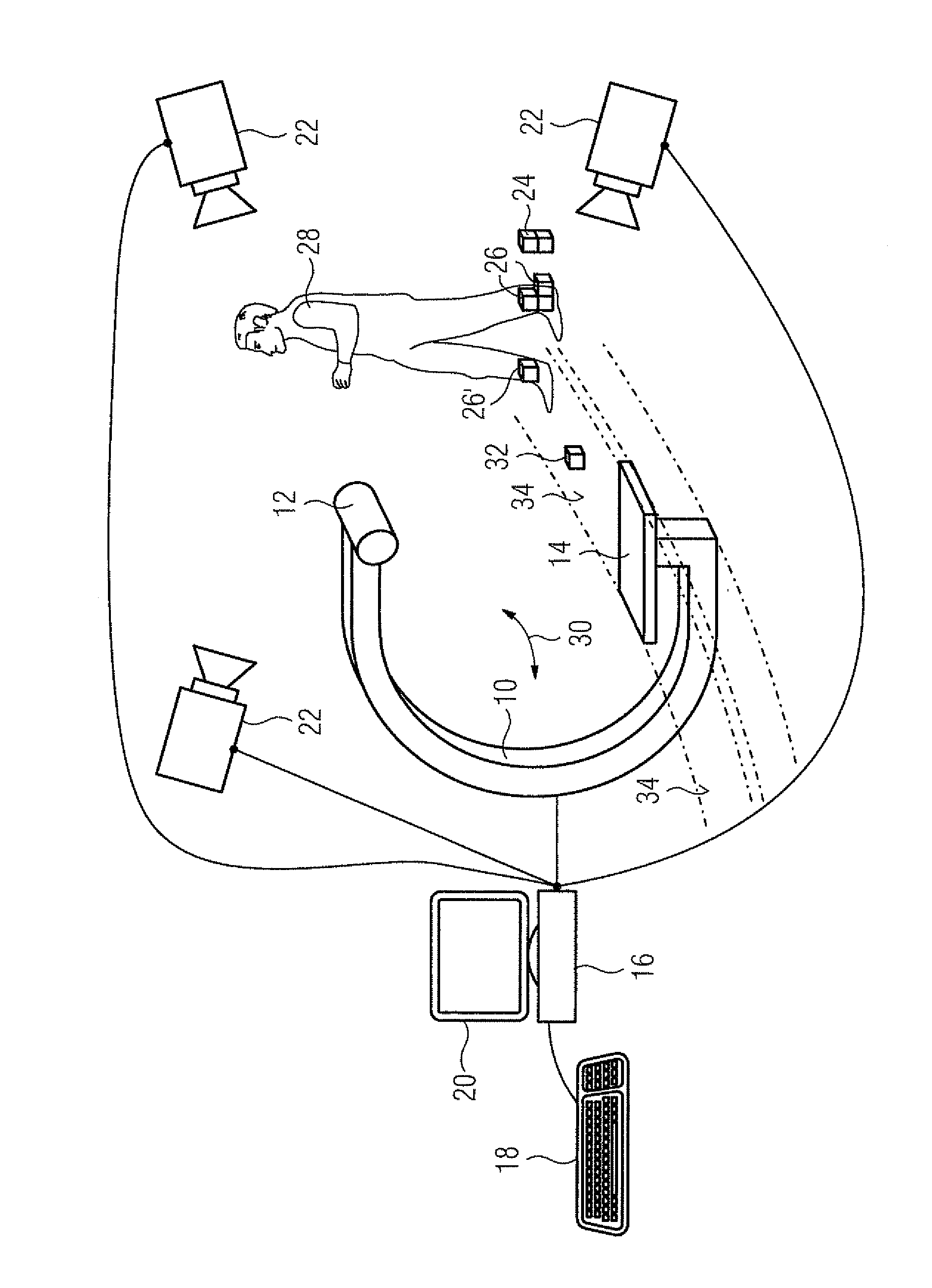
[0024]An x-ray C-arm system 10 is arranged in a treatment room, of which only the x-ray C-arm 10 with x-ray source 12 and x-ray flat panel detector 14 is shown by way of representation in the FIGURE. The movements of the x-ray C-arm are controlled by a control facility 16. The control facility 16 receives input signals by way of an input facility 18. By way of example, a joystick is shown for the input facility, the inputs can take place in a manner known also by way of pushbuttons, a computer mouse or a keyboard. Useful displays are shown on a monitor 20 for an operator.

[0025]A patient couch, upon which a patient rests during the operation, conventionally forms part of the x-ray C-arm. For reasons of clarity, the patient couch and patient are omitted in the FIGURE. A plurality of video cameras 22 is now arranged in the space in which the x-ray C-arm system is positioned. Three such video cameras 22 are shown in the FIGURE, the inventive system then operates particularly expediently...


PUM


Abstract

With an x-ray imaging system with a moveable part, obstacles can stand in the way of the movement of the moveable part. In accordance with the invention, video cameras capture the occupation of the space by objects using volume elements. It is possible to determine at a target movement of the moveable part which volume elements are passed through during this. If one of these volume elements proves to be a volume element occupied by an object, the movement of the moveable part is prevented, otherwise it is enabled or actively implemented.

Description

CROSS REFERENCE TO RELATED APPLICATIONS[0001]This application claims priority of German application No. 10 2007 032 540.3 filed Jul. 12, 2007, which is incorporated by reference herein in its entirety.FIELD OF THE INVENTION[0002]The invention relates to a method for controlling the movement of a moveable part of an x-ray imaging system as well as an x-ray imaging system.[0003]The x-ray imaging system can be a conventional x-ray C-arm system and the moveable part is then the x-ray C-arm. The invention is also used in an x-ray imaging system, with which the x-ray tube and x-ray detector are moved by a robot.BACKGROUND OF THE INVENTION[0004]Modem x-ray imaging systems, in particular the x-ray C-arm systems, allow a plurality of movements of the respective moveable part. It is not easy for an operator to predict whether or not the moveable part meets with an obstacle during its movement. Such an obstacle can be the patient him / herself, an instrument table with instruments for performing...

Claims


Application Information

Patent Timeline
Patent Type & Authority Patents(United States)
IPC IPC(8): H04N5/253H04N5/225
CPCA61B6/102A61B6/547A61B6/461
Inventor KLINGENBECK-REGN, KLAUS
Owner SIEMENS HEALTHCARE GMBH
Learn More